Metal cutting machine tool

A metal cutting and machine tool technology, which is applied in metal processing machinery parts, metal processing, metal processing equipment, etc., can solve the problems of affecting the use of devices, debris splashing, difficult collection, etc., and achieve the effect of reducing jitter and moving conveniently

Pending Publication Date: 2021-02-12
闫玉乐
View PDF1 Cites 0 Cited by
  • Summary
  • Abstract
  • Description
  • Claims
  • Application Information

AI Technical Summary

Problems solved by technology

[0006] In order to solve the technical problems in the background technology, the present invention proposes a metal cutting machine tool, which solves the problem that some debris will splash during cutting, which is not easy to collect, and then affects the use of the device

Method used


Image

  • Metal cutting machine tool
  • Metal cutting machine tool
  • Metal cutting machine tool

Examples


Embodiment 1

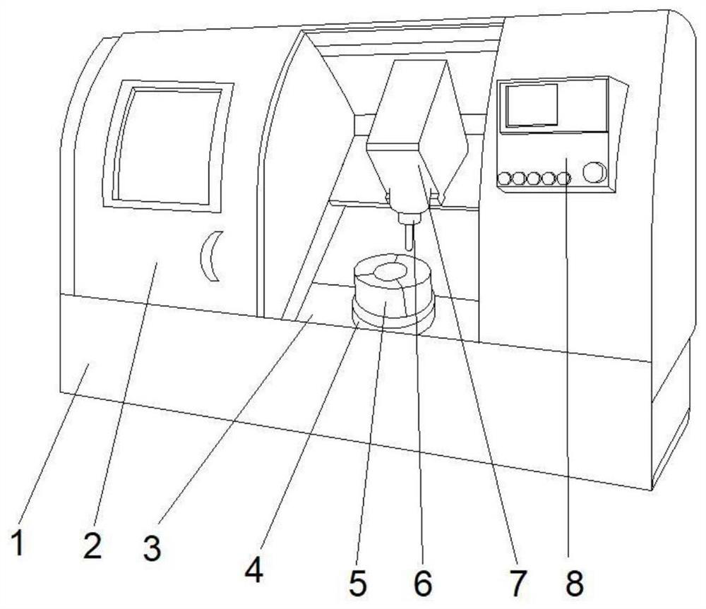
[0035] like Figure 1-2 , a technical solution proposed by the present invention: a metal cutting machine tool, including a main body 1, a working chamber 3 is provided in the middle of the front top of the main body 1, a box door 2 is arranged on the left side of the front top of the main body 1, and the front of the main body 1 The right side of the top is fixedly connected with a controller 8, the top of the inner chamber of the working chamber 3 is provided with a working mechanism 7, the front bottom of the working mechanism 7 is fixedly connected with a cutter 6, and the middle position of the inner chamber bottom of the working chamber 3 is fixedly connected with a communication device 4 , the top of the communication device 4 is fixedly connected with a transition device 5 .

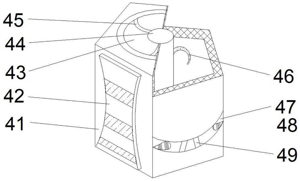
[0036] Wherein, the communication device 4 includes a casing 41, the bottom left side of the front of the casing 41 is fixedly connected with a bottom plate 42, the right side of the front bottom...

Embodiment 2

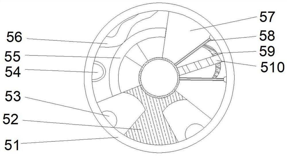
[0039] like Figure 1-3 As shown, on the basis of Embodiment 1, the present invention provides a technical solution: the transition device 5 includes an outer frame 51, the bottom of the outer frame 51 is fixedly connected with a top plate 52, and the bottom of the outer frame 51 is located on both sides of the top plate 52. The side is fixedly connected with a communication hole, the middle part of the left side of the outer frame 51 is provided with a rotating ring 55, the position of the outer frame 51 close to the rotating ring 55 is fixedly connected with a wave plate 56, and the position of the outer frame 51 close to the communication hole is fixedly connected with an elastic ball 54 The middle part of the right side of the outer frame 51 is fixedly connected with a connecting fixed rod 510, and the two sides of the connecting fixed rod 510 are fixedly connected with a swing rod 58, and an arc-shaped slider 59 is arranged between the supported swing rod 58 and the connec...

Embodiment 3

[0042] like Figure 1-6 As shown, on the basis of Embodiment 1 and Embodiment 2, the present invention provides a technical solution: the inner walls on both sides of the bottom plate 42 are fixedly connected with fixed plates 424, and the positions between the tops of the fixed plates 424 are fixedly connected with fixed seats 423 A support block 422 is fixedly connected to the top of the fixing seat 423 , and a groove 421 is fixedly connected to the top of the support column 422 .

[0043] Wherein, the front top of the arc block 46 is provided with a turning arc 461, the front middle part of the arc block 46 is provided with a leakage hole 462, and the front bottom of the arc block 46 is fixedly connected with a contact post 464, and the arc block 46 is close to the contact post 464 The position is fixedly connected with fixed teeth 463 .

[0044] Wherein, the top plate 52 includes a connecting frame 522, a guide groove 524 is opened at the middle position of the bottom of ...


PUM


Abstract

The invention discloses a metal cutting machine tool. The metal cutting machine tool comprises a main body, wherein a working cavity is formed in the middle of the top of the front face of the main body; a box door is arranged on the left side of the top of the front face of the main body; a controller is fixedly connected to the right side of the top of the front face of the main body; a workingmechanism is arranged at the top of an inner cavity of the working cavity; a cutter is fixedly connected to the bottom of the front face of the working mechanism; a communicating device is fixedly connected to the middle position of the bottom of the inner cavity of the working cavity; and a transition device is fixedly connected to the top of the communicating device. The invention relates to thetechnical field of the metal cutting machine tool. According to the metal cutting machine tool, a workpiece is cut in the working cavity, trace cutting is conducted during cutting, cut chippings areconvenient to collect, and the chippings are not prone to splashing everywhere; the service life of the metal cutting machine tool is prolonged; the surface of a contact column is provided with fixingthreads, so that friction is increased during contact, the contact column can be matched with fixing teeth conveniently, thus, the fixing is conducted, and the shaking phenomenon is not prone to occurring after fixing; and loosening is convenient, and damage to the device is reduced.

Description

technical field [0001] The invention relates to the technical field of metal cutting machine tools, in particular to a metal cutting machine tool. Background technique [0002] Metal cutting machine tools are machine tools (except portable ones) that process various metal workpieces by cutting, grinding or special processing methods to obtain the required geometric shape, dimensional accuracy and surface quality. Metal cutting machine tools are the most widely used and most numerous category of machine tools. There are many classification methods for metal cutting machine tools. The most commonly used classification method is to classify according to the processing properties of the machine tool and the tools used; in addition, it can also be classified according to the degree of versatility of the lathe, the working accuracy of the machine tool, the weight and size, the number of main organs of the machine tool, and the degree of automation. sort. The scale of the metal c...

Claims


Application Information

Patent Timeline
Patent Type & Authority Applications(China)
IPC IPC(8): B23Q37/00B23Q11/00
CPCB23Q11/0042B23Q37/00
Inventor 闫玉乐
Owner 闫玉乐
Why Eureka
Try Eureka