Special built-in frame for aerospace liquid propeller

An aerospace and propulsion technology, which is applied in the field of special built-in racks for aerospace liquid thrusters, can solve the problems of easy damage, huge vibration of the propeller, and no engine electronic regulator to buffer the built-in rack.

Inactive Publication Date: 2021-02-12
凌亚
View PDF0 Cites 0 Cited by
  • Summary
  • Abstract
  • Description
  • Claims
  • Application Information

AI Technical Summary

Problems solved by technology

[0003] The engine electronic regulator in the propeller plays the role of regulating the circuit. The propeller will generate huge vibration during the working process. If the engine electronic regulator is not protected by a buffer device, it is easy to be damaged. Currently, there is no special engine electronic regulator. Cushioned built-in frame, now offering a dedicated built-in frame for aerospace liquid propulsion

Method used


Image

  • Special built-in frame for aerospace liquid propeller
  • Special built-in frame for aerospace liquid propeller
  • Special built-in frame for aerospace liquid propeller

Examples


Embodiment 1

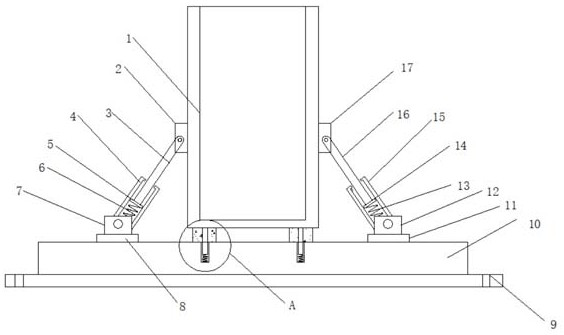
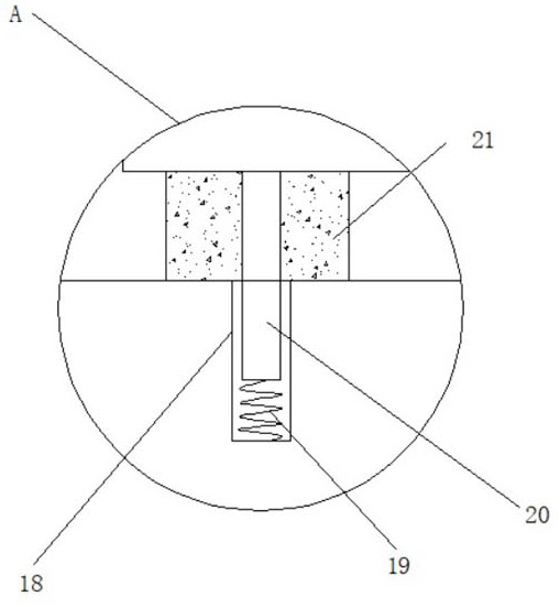
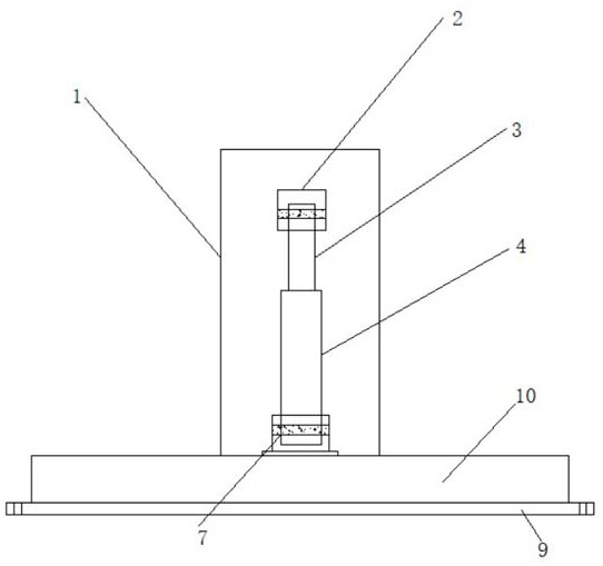
[0021] Embodiment 1, with reference to Figure 1-3 , a special built-in frame for aerospace liquid propulsion, comprising a carrying case 1, a bottom plate 10 is installed at the bottom of the carrying case 1, a first buffer mechanism is installed on one side of the carrying case 1 and the top side of the bottom plate 10, the carrying case The other side of 1 and the other side of the top of base plate 10 are equipped with a second buffer mechanism, and a connecting mechanism is installed between the bottom end of carrying case 1 and the top of base plate 10. The first buffer machine includes a top end mounted on base plate 10. The first fixed block 7 on the side, the top of the first fixed block 7 is movably installed with the first sleeve 4 through the pin shaft, the first movable rod 3 is movably connected in the first sleeve 4, and the outer wall of one side of the bearing box 1 The second fixed block 2 is welded, and the top of the first movable rod 3 is movably connected...


PUM


Abstract

The invention discloses a special built-in frame for an aerospace liquid propeller. The frame comprises a bearing box, a bottom plate is mounted at the bottom end of the bearing box, a first buffer mechanism is mounted on one side of the bearing box and one side of the top end of the bottom plate, and a second buffer mechanism is mounted on the other side of the bearing box and the other side of the top end of the bottom plate; and a connecting mechanism is installed between the bottom end of the bearing box and the top end of the bottom plate, the first buffer machine comprises a first fixingblock installed on one side of the top end of the bottom plate, and a first sleeve is movably installed at the top end of the first fixing block through a pin shaft. A first compression spring playsa role in pulling and supporting a first pressing plate so that a first movable rod moves in a first sleeve, and a second compression spring plays a role in pulling and supporting a second pressing plate so that a second movable rod moves in a second sleeve; and then through the first movable rod and the second movable rod, the two sides of the bearing box achieve a support effect, and the buffering effect is realized.

Description

technical field [0001] The invention relates to the technical field of aerospace propulsion, in particular to a special built-in frame for aerospace liquid propulsion. Background technique [0002] In terms of physical form, there are two forms of propellant used in aerospace liquid propulsion, one is liquid substance and the other is solid substance. The engine in which both the combustion agent and the oxidizer are in liquid form is called a liquid fuel engine. , or known as a liquid rocket motor, both of which are in a solid state, are called solid fuel rocket motors or solid rocket motors. If one of the two fuels is solid and the other is liquid, it is called a solid-liquid rocket engine or a rocket engine directly named by its substance, such as a hydrogen-oxygen rocket engine. Since the energy generated by the solid combustion agent is higher than the energy emitted by the liquid oxidant, most of the rocket engines developed are solid-liquid rocket engines. The two fu...

Claims


Application Information

Patent Timeline
Patent Type & Authority Applications(China)
IPC IPC(8): B64G5/00
CPCB64G5/00
Inventor 凌亚
Owner 凌亚
Why Eureka
Try Eureka