Cathode lock

A cathode lock and lock lever technology, applied in the field of locks, can solve the problems of reducing the use effect of the overall structure, unfavorable remote operation control, affecting customer use experience, etc., and achieve the effect of avoiding excessive bounce and ensuring the position.

Pending Publication Date: 2021-02-12
ZHEJIANG HONGTAI ELECTRONICS EQUIP
View PDF0 Cites 0 Cited by
  • Summary
  • Abstract
  • Description
  • Claims
  • Application Information

AI Technical Summary

Problems solved by technology

Existing cathode locks mainly include a housing, a deadbolt, a lock bar, a lock catch and an electromagnet. The friction restricts the movement of the lock rod on the lock rod, so that when the lock tongue is forced to rotate, due to the resistance of the lock buckle, the lock rod cannot be driven to swing, forming an unlocking action. The rod can be moved by the rotation of the lock tongue to form an unlocking action, but this kind of cathode lock will be kept in the electromagnet for a certain period of time, and then the power will be cut off. It can be reset, and the resistance is on the lock rod, which forms a resistance to the lock rod again. Sometimes, when the electromagnet is energized, it is operated by internal personnel, and the requester often has no time to open the door. The electromagnet is powered off and the lock is reset. However, it is difficult for the current cathode lock to realize the mechanical reset of the lock after the lock tongue is operated, which reduces the use effect of the overall structure and affects the customer experience.

Method used


Image

  • Cathode lock
  • Cathode lock
  • Cathode lock

Examples


Embodiment Construction

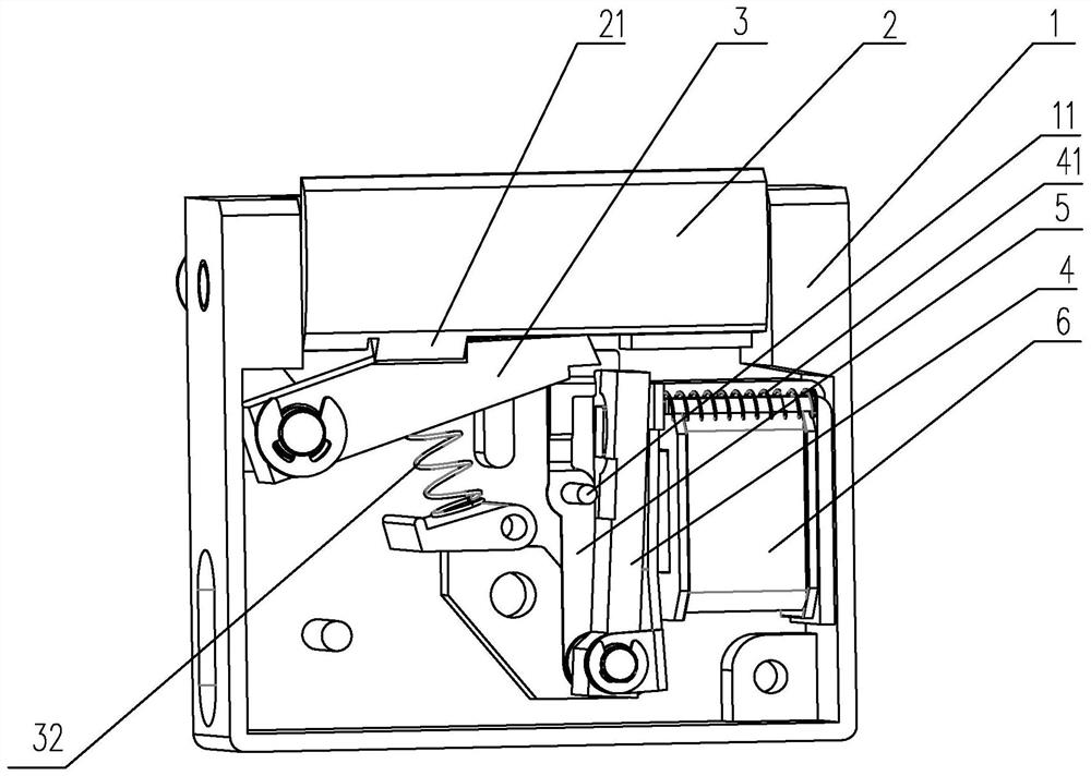
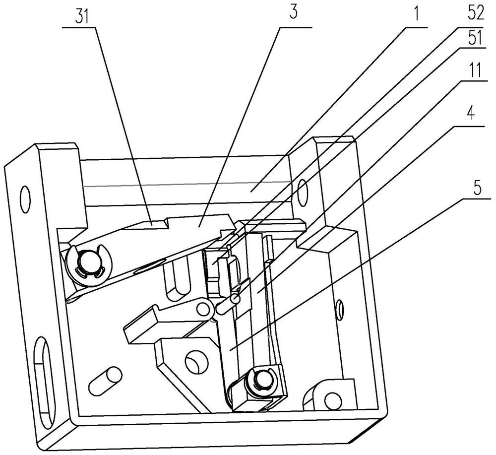
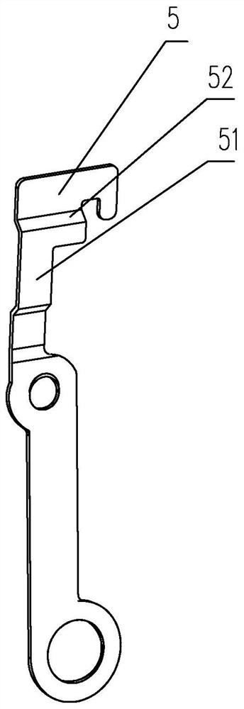
[0015] The embodiment of cathode lock of the present invention is such as Figure 1 to Figure 3 Shown: includes housing 1, lock tongue 2, lock rod 3, lock catch 4 and electromagnet 6, the lock tongue 2 is rotatably arranged on the housing 1, and the lock rod 3 and lock catch 4 are hingedly arranged on the shell In the body 1, the lock bar 3 is arranged on one side of the lock tongue 2, and a chute 31 and a flange 21 are arranged between the lock bar 3 and the lock tongue 2, and the flange 21 and the chute 31 are set in conflict to form The rotation of the lock tongue 2 drives the lock rod 3, and the conflict spring 32 for resetting the lock rod 3 is in contact between the lock rod 3 and the inner wall of the housing 1. The electromagnet 6 is arranged on the side of the lock catch 4, and the Between the lock catch 4 and the side wall of the electromagnet 6, there is still a conflict between the reset spring 41 for resetting the lock catch 4, and a limit spring 5 is also arrange...


PUM


Abstract

The invention discloses a cathode lock. The cathode lock comprises a shell, a lock tongue, a lock rod, a lock catch and an electromagnet, wherein the lock tongue is rotationally arranged on the shell,the lock rod and the lock catch are hinged in the shell, the lock rod is arranged on one side of the lock tongue, an inclined groove and a flange are arranged between the lock rod and the lock tongue, an abutting spring is arranged between the lock rod and the inner wall of the shell in an abutting mode, the electromagnet is arranged on one side of the lock catch, a reset compressed spring is arranged between the lock catch and the side wall of the electromagnet in an abutting mode, a limiting elastic piece is arranged between the lock rod and the lock catch, an abutting protrusion is arranged on the limiting elastic piece, and the limiting elastic piece has an unlocking state, a transition state, a reset state and a locking state. When the lock tongue is not operated to unlock, the lockcatch cannot be reset to abut against the lock rod, and after unlocking operation is completed, the lock catch can be reset to lock the lock rod again, so that the using effect of a whole structure iseffectively improved.

Description

technical field [0001] The invention relates to the technical field of locks, in particular to a cathode lock. Background technique [0002] The working principle of the cathode lock is similar to that of the anode lock (electric mortise lock). Compared with cathode locks, cathode locks and anode locks are used in a smaller range, and are usually used for the installation of ordinary wooden doors. The bolt of the wooden door is clamped by the notch of the cathode lock to achieve the function of locking the door. The cathodic lock is a supporting product of the access control system. It is generally installed on the door frame to lock the mechanical deadbolt; the cathodic lock can be widely used in office buildings, wooden doors, stainless steel doors, fire doors, community entrance and exit gates, and anode mechanical locks Or the ball lock is used together. Existing cathode locks mainly include a housing, a deadbolt, a lock bar, a lock catch and an electromagnet. The fri...

Claims


Application Information

Patent Timeline
Patent Type & Authority Applications(China)
IPC IPC(8): E05B15/00E05B47/00E05B47/06
CPCE05B15/00E05B47/0002E05B47/0607
Inventor 许君淮张敏德
Owner ZHEJIANG HONGTAI ELECTRONICS EQUIP
Why Eureka
Try Eureka