
Axial flow compressor stationary blade adjusting mechanism and axial flow compressor applying same

A technology of axial flow compressor and adjustment mechanism, which is applied in the field of axial flow compressors, can solve the problems of limited adjustment speed, unfavorable compressor quick adjustment response, difficulty in realizing fast adjustment of stator vane angle, etc., and achieve the effect of improving the adjustment speed

Pending Publication Date: 2021-02-12
CHENGDU CHENGFA SCI & TECH POWER ENG
View PDF0 Cites 0 Cited by
  • Summary
  • Abstract
  • Description
  • Claims
  • Application Information

AI Technical Summary

Problems solved by technology

For the rack and pinion vane adjustment mechanism, its adjustment sensitivity is low and the adjustment accuracy is poor; the hydraulic drive vane adjustment mechanism has a fast adjustment speed, but it needs to be equipped with a special power oil station system, and the structure is complex, troublesome in use and maintenance, and prone to accidents. Faults such as drifting and crawling; the rotary electric actuator drives the stator blade adjustment mechanism, and its adjustment speed is limited, making it difficult to quickly adjust the angle of the stator blades, which is not conducive to the rapid adjustment response of the compressor in emergencies

Method used


Image

  • Axial flow compressor stationary blade adjusting mechanism and axial flow compressor applying same
  • Axial flow compressor stationary blade adjusting mechanism and axial flow compressor applying same
  • Axial flow compressor stationary blade adjusting mechanism and axial flow compressor applying same

Examples


Embodiment Construction

[0025] In order to better understand the purpose, structure and function of the present invention, the stator vane adjustment mechanism of the axial flow compressor of the present invention and the axial flow compressor applying it will be further described in detail below in conjunction with the accompanying drawings.

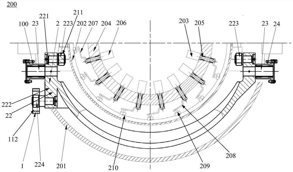
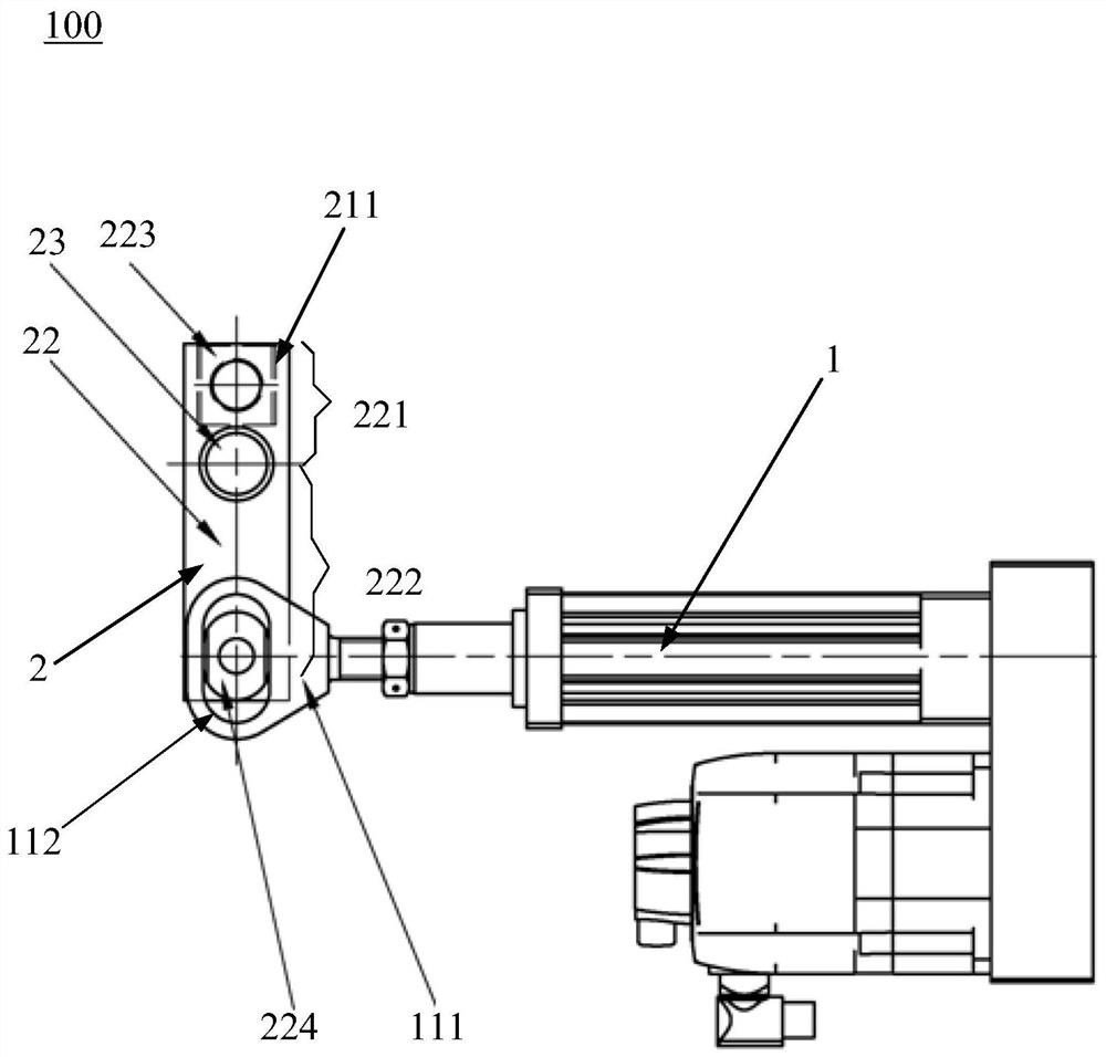
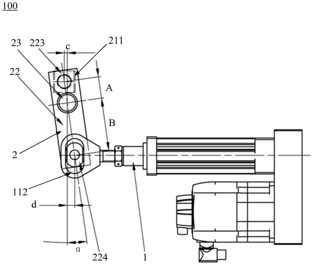
[0026] Figure 1 to Figure 3 The structure of the vane adjustment mechanism 100 of the axial flow compressor according to the embodiment of the present invention is shown. The stator vane adjustment mechanism 100 of the axial flow compressor includes: an actuator 1, a linkage half-ring assembly 2, the linkage half-ring assembly 2 includes a positioning shaft 23 and a linkage half-ring 22 capable of rotating around the positioning shaft 23, the linkage half-ring 22 includes The first linkage arm 221 and the second linkage arm 222 located on both sides of the positioning shaft 23, the first linkage arm 221 is used to connect with the adjustment cylinder 202 of t...


PUM


Abstract

The invention belongs to the technical field of axial flow compressors, and discloses an axial flow compressor stationary blade adjusting mechanism capable of increasing the adjusting speed of the stationary blade angle of an axial flow compressor and the axial flow compressor applying the axial flow compressor stationary blade adjusting mechanism. The axial flow compressor stationary blade adjusting mechanism comprises an executing component and a linkage semi-ring assembly, the linkage semi-ring assembly comprises a positioning shaft and a linkage semi-ring capable of rotating around the positioning shaft, the linkage semi-ring comprises a first linkage arm and a second linkage arm which are located at the two sides of the positioning shaft respectively, and the first linkage arm is usedfor being connected with an adjusting cylinder of the axial flow compressor; and the adjusting cylinder is connected with a stationary blade assembly of the axial flow compressor, the second linkagearm is connected with the executing component, and the executing component is configured to linearly push the second linkage arm to rotate around the positioning shaft in the axial direction of the linkage semi-ring so as to drive the first linkage arm to reversely rotate around the positioning shaft, so that the adjusting cylinder connected with the first linkage arm is driven to move axially, sothat the adjusting cylinder drives a stationary blade of the stationary blade assembly to rotate.

Description

technical field [0001] The invention belongs to the technical field of axial flow compressors, and in particular relates to a vane adjustment mechanism of an axial flow compressor and an axial flow compressor using the same. Background technique [0002] Axial flow compressor is a kind of turbo mechanical equipment that provides compressed gas. It is often used for large-scale air supply and gas compression in smelting, petroleum, chemical, fermentation, environmental protection, air separation and other industries. When the axial flow compressor is used, due to changes in its inlet conditions (atmospheric pressure, temperature, etc.) or changes in the flow rate and pressure at the compressor outlet required by the process, it is necessary to change the operating conditions of the axial flow compressor. It is realized by changing the vane angle of the axial flow compressor. [0003] Existing stator vane adjustment mechanisms for axial flow compressors include: a rack and pi...

Claims


Application Information

Patent Timeline
Patent Type & Authority Applications(China)
IPC IPC(8): F04D29/56F04D27/00F04D19/00
CPCF04D19/00F04D27/002F04D29/563F05D2270/62
Inventor 师亚洲罗文瑞高见范东升柘博文
Owner CHENGDU CHENGFA SCI & TECH POWER ENG
Learn More