
Kelly bar plug valve and method

A technology of cock valve and kelly, which is applied in the direction of earth square drilling, cock including cutting device, valve details, etc. It can solve the problems of high cost, trouble, and stuck valve core to open and close the valve, and save labor in opening and closing And convenient, easy to use, reduce the effect of rotation resistance

Inactive Publication Date: 2021-02-12
孙肖
View PDF0 Cites 0 Cited by
  • Summary
  • Abstract
  • Description
  • Claims
  • Application Information

AI Technical Summary

Problems solved by technology

[0004] In the existing kelly plug valve, in order to ensure the sealing effect, the contact area between the valve core, the valve body and the valve seat is very large. When the valve core receives huge pressure, it will take a lot of force to open the valve, and it may The spool is stuck; and the opening of the valve must use a wrench, which makes it particularly troublesome

Method used

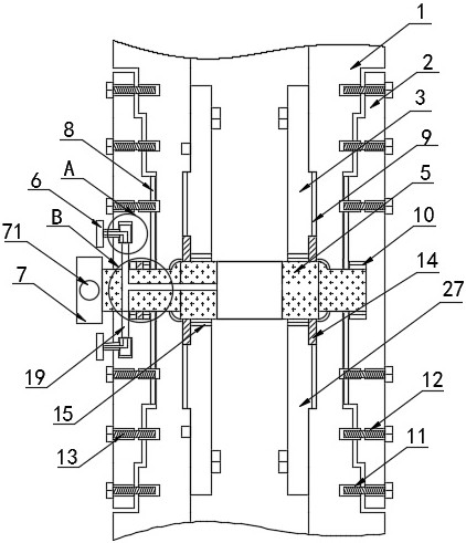

Image

  • Kelly bar plug valve and method
  • Kelly bar plug valve and method
  • Kelly bar plug valve and method

Examples


Embodiment 1

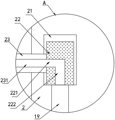
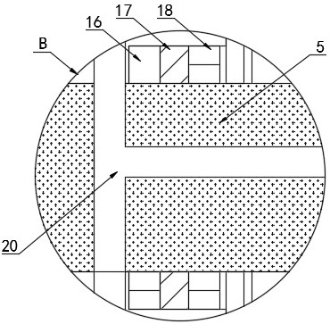
[0036] Refer to the attached Figure 1-5 , a kelly cock valve and its method in this embodiment, comprising an outer valve body 2, an inner valve body 1, an upper valve seat 3, a lower valve seat 27, a spherical valve core 5, a bearing 10 and a screw 13, the outer valve body The valve body 2 and the inner valve body 1 are provided with two groups, the outer wall of the outer valve body 2 is fixedly installed with an arc-shaped guide rod 24, the inner side of the outer valve body 2 abuts against the inner valve body 1, and the outer valve body 2 2. There is a sealing ring 1 between the inner valve body 1. The inner side of the inner valve body 1 at the upper end abuts against the upper valve seat 3, and the inner side of the inner valve body 1 at the lower end abuts against the lower valve seat 27. A sealing ring 2 is provided between the inner valve body 1, the upper valve seat 3 and the lower valve seat 27, and the right end of the spherical valve core 5 is fixedly installed ...

Embodiment 2

[0049] Refer to the attached Figure 6-7 , and the difference from Example 1 is that: the outer valve body 2 is provided with an internally threaded hole 12, and the internal valve body 1 is provided with an internally threaded hole 2 11;

[0050] The specific implementation scenarios are:

[0051] When installing, install according to the installation method on the left side of Example 1, and finally insert the U-shaped driving rod 26 on the insertion rod 71 of the switch knob 7 at the left and right ends. When opening and closing the valve, insert the U-shaped driving rod 26 26 Pull up and down to the end.


PUM


Abstract

The invention discloses a kelly bar plug valve and a method. According to the technical scheme, two sets of outer valve bodies, two sets of inner valve bodies, an upper valve seat, a lower valve seat,a spherical valve element, bearings and screws are included, arc-shaped guide rods are fixedly installed on the outer walls of the outer valve bodies, and the inner sides of the outer valve bodies abut against the inner valve bodies. First sealing rings are arranged between the outer valve bodies and the inner valve bodies, the inner side of the inner valve body at the upper end abuts against theupper valve seat, and the inner side of the inner valve body at the lower end abuts against the lower valve seat. The kelly bar plug valve and the method have the beneficial effects that by arranginga T-shaped hole, a communicating hole, a cock hole, a connecting hole and a pressure relief hole, before the valve is opened, a pressure relief knob is driven to rotate, so that the T-shaped hole, the communicating hole, the cock hole, the connecting hole and the pressure relief hole are in communication for pressure relief, accordingly the internal and external pressure intensity difference is reduced, the spherical valve element rotates more smoothly, a driving rod is arranged, a switch knob does not need to be screwed by using a wrench, and opening and closing of the valve are more convenient in a labor-saving manner.

Description

technical field [0001] The invention relates to the technical field of kelly cock valves, in particular to a kelly cock valve and a method thereof. Background technique [0002] The plug valve is a closing member or a plunger-shaped rotary valve. By rotating 90 degrees, the channel port on the valve plug communicates with or separates from the channel port on the valve body to realize opening or closing. The shape of its valve plug It can be cylindrical or conical. In the cylindrical valve plug, the channel is generally rectangular; in the conical valve plug, the channel is trapezoidal. These shapes make the structure of the plug valve light and suitable for cutting and connecting. It is suitable for passing medium and shunting, but according to the applicable properties and the erosion resistance of the sealing surface, sometimes it can also be used for throttling. The plug valve is a fast-switching straight-through valve. Because the movement between the sealing surfaces h...

Claims


Application Information

Patent Timeline
Patent Type & Authority Applications(China)
IPC IPC(8): F16K5/06F16K5/08F16K27/06F16K31/60F16K39/06E21B34/14
CPCE21B34/14F16K5/0605F16K5/0626F16K5/0647F16K5/08F16K27/067F16K31/60F16K39/06
Inventor 孙肖刘佳孟令君李萧王厉强王艳丽
Owner 孙肖
Learn More