Stress relieving structure and design method for integrated design of multi-stage compressor unit

A technology of stress relief and integrated design, applied in the direction of mechanical equipment, machines/engines, liquid variable capacity machinery, etc., can solve the problem of difficulty in centralized pipeline arrangement, and achieve the solution of pipeline stress, compressor nozzle load, and pipeline direction Simplicity, effect of reducing pipe length and number of elbows

Pending Publication Date: 2020-08-07
CHINA CHENGDA ENG
View PDF0 Cites 0 Cited by
  • Summary
  • Abstract
  • Description
  • Claims
  • Application Information

AI Technical Summary

Problems solved by technology

[0004] In order to solve the above-mentioned technical problem that it is difficult to centrally arrange the pipes of the existing integrated design equipment, the purpose of the present invention is to provide a stress relief structure and design method for the integrated design of multi-stage compressor units. The purpose is to use the spring combination structure to absorb and Coordinating the displacement and deformation of each pipeline can not only effectively bear the weight of interstage equipment and pipelines, but also make the interstage equipment and pipelines form a whole and adopt natural compensation methods to solve pipeline stress, so that pipeline stress and load do not exceed the allowable value , in order to achieve the purpose of minimizing the length of the pipeline and the number of elbows, realize the optimal integrated design of the compressor unit, ensure the normal operation of the compressor, and effectively and greatly improve the working efficiency of the compressor

Method used


Image

  • Stress relieving structure and design method for integrated design of multi-stage compressor unit
  • Stress relieving structure and design method for integrated design of multi-stage compressor unit
  • Stress relieving structure and design method for integrated design of multi-stage compressor unit

Examples


Embodiment 2

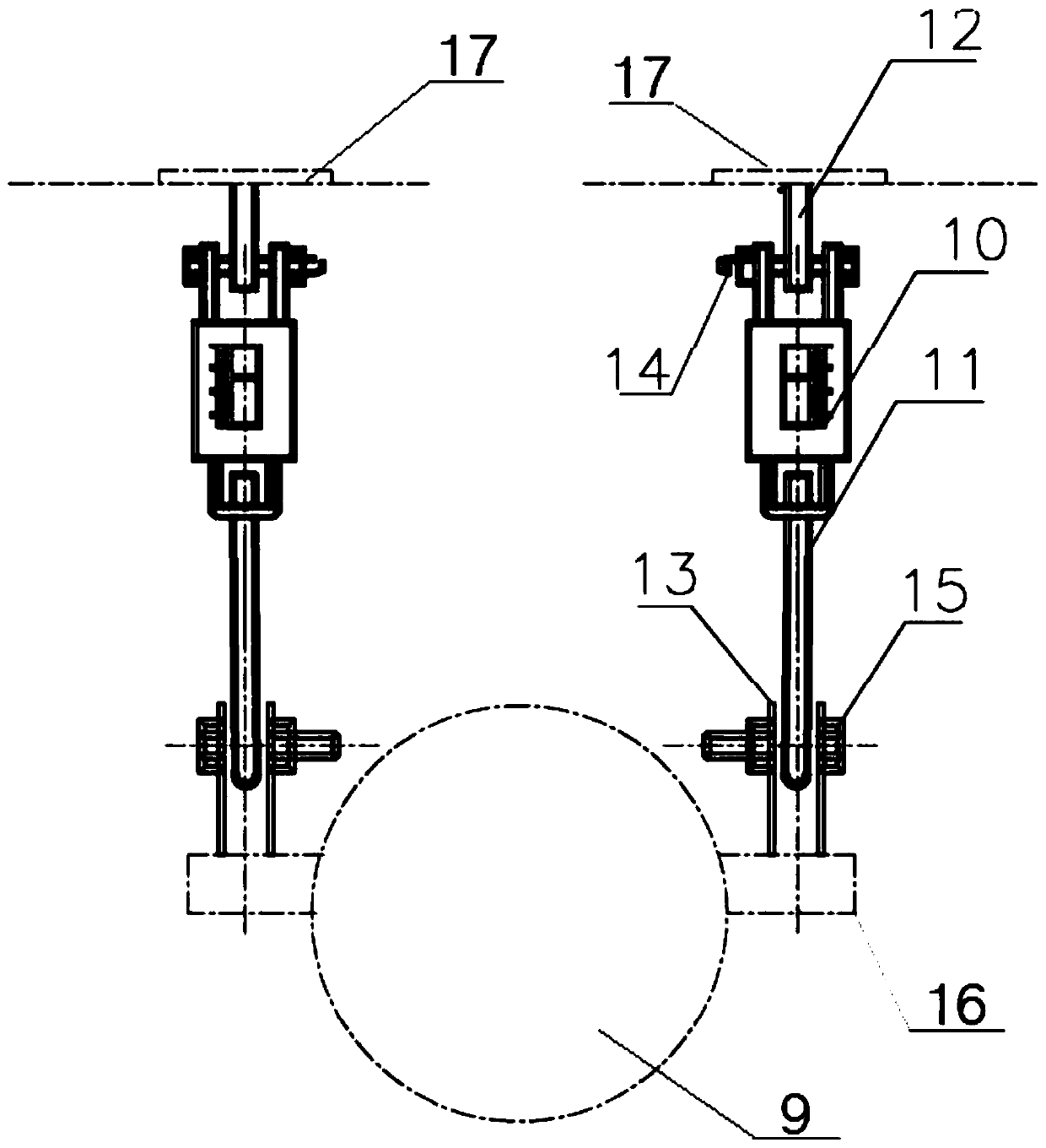
[0039] The second embodiment is basically the same as the first embodiment, except that the corresponding positions of the spring body 10 and the suspension rod 11 of the spring hanger in the spring combination structure provided by this embodiment are designed differently (not shown), and the spring hanger includes The spring body 10 and the suspender 11 connected to the upper end of the spring body 10, the lower end of the spring body 10 is hinged to the second lug, and the upper end of the suspender 11 is hinged to the first lug; correspondingly, the first lug is a double-plate hanger The second lug is a single-plate lug, and there is a lug hole at the lower end of the double-plate lug, so that the upper end of the suspension rod 11 in the spring hanger is hinged on the double-plate lug through the corresponding lug hole through the bolt load-bearing pin The upper end of the veneer lug has a lug hole, so that the lower end of the spring body 10 in the spring hanger is hinged...

Embodiment 3

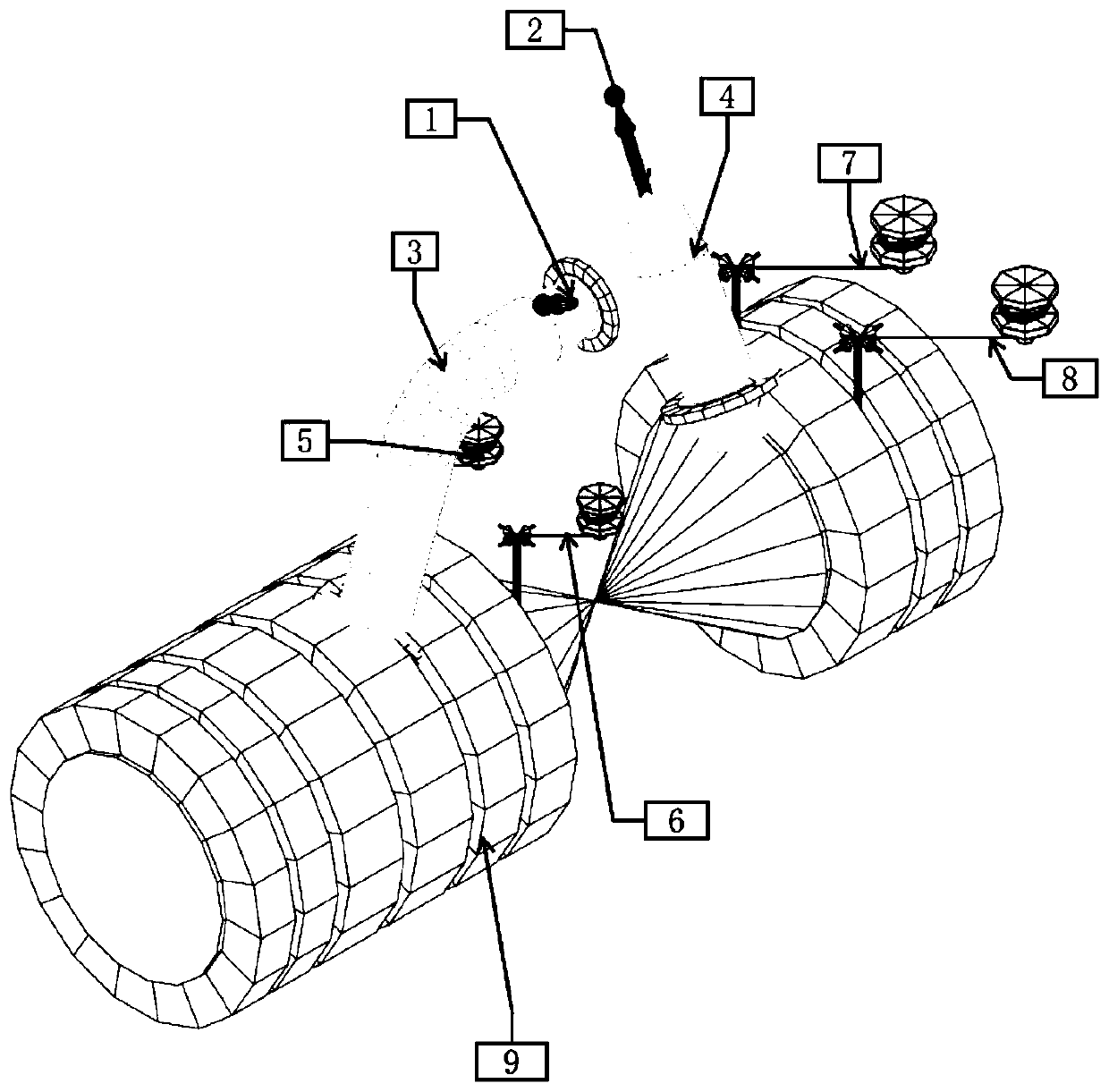
[0041] on the other hand, figure 1 It shows the principle diagram of the layout of the stress relief structure for the integrated design of the multi-stage compressor unit in an exemplary embodiment of the present invention. According to the present invention, this embodiment also provides a stress relief design method for the integrated design of the multi-stage compressor unit, which Applying the stress relief structure in Embodiment 1, the stress relief design method comprises the following steps:

[0042] S1, determine the position of the compressor, including its plane position and installation height;

[0043] S2, determine the position of the interstage equipment (cooler) 9, so that the interstage equipment is arranged near the position directly below the nozzle of the corresponding compressor;

[0044] S3, determine the direction of the connecting pipeline according to the nozzle of the interstage equipment and the corresponding compressor nozzle, and the direction of...

comparative approach 1

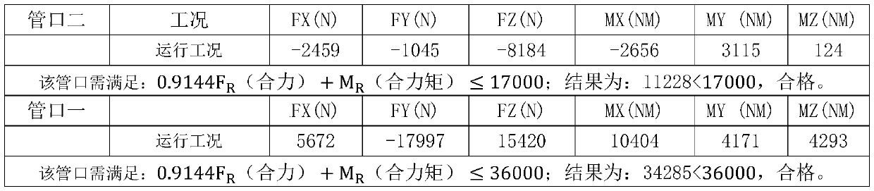
[0051] Comparison Scheme 1: Fully adopt the stress relief structure in Embodiment 1, that is, in figure 1 The supporting lugs at both ends of the shown interstage equipment are provided with spring hanger 1 5, spring hanger 2 6, spring hanger 3 7 and spring hanger 4 8, and the overall stress analysis results after installation are shown in Table 1. It fully meets the requirements of engineering specifications.

[0052] Table 1 fully adopts the stress and moment analysis results of the compressor nozzle of the stress relief structure of Embodiment 1

[0053]


PUM


Abstract

The invention discloses a stress relieving structure and design method for integrated design of a multi-stage compressor unit, and relates to the technical field of integrated design of multi-stage compressor units. The stress relieving structure comprises a spring combination structure and a spring installation support, wherein the spring combination structure comprises a plurality of spring hangers arranged on interstage equipment supporting lugs, a first lifting lug is arranged on the spring installation support, and a second lifting lug is arranged on the interstage equipment supporting lugs, so that interstage equipment is arranged at the position close to the position under a corresponding compressor pipe opening, and the spring hangers are used for bearing and hanging the interstageequipment. Through implementing the technical scheme, the technical problem of high difficulty in centralized arrangement of pipelines of existing integrated design equipment can be solved; and displacement and deformation of all pipelines are absorbed and coordinated through the spring combination structure, so that the stress and load of the pipelines do not exceed allowable values, the purposeof reducing the length of the pipelines and the number of elbows to the maximum extent is achieved, the optimized compressor unit integration design is achieved, normal operation of a compressor is guaranteed, and the working efficiency of the compressor is greatly improved.

Description

technical field [0001] The invention relates to the technical field of integrated design of multi-stage compressor units, and more specifically, relates to a stress relief structure and design method for the integrated design of multi-stage compressor units. Background technique [0002] In the field of petrochemical technology, compressors are usually large energy consumers, and multi-stage compressors are the most common form of large-scale compressors. Multi-stage compressor units are widely used in petrochemical equipment. By compressing the medium, the The medium reaches the required pressure. However, due to the large number of inter-stage equipment and pipelines in multi-stage compressor units, the layout of traditional multi-stage compressor unit equipment and pipelines is complicated. The unit equipment is rigidly supported. In this way, both ends of each pipe of the unit are completely fixed, which requires the pipe to have sufficient length in all directions and ...

Claims


Application Information

Patent Timeline
Patent Type & Authority Applications(China)
IPC IPC(8): F04B39/12F04B39/14F04B39/00F04B37/12
CPCF04B37/12F04B39/00F04B39/123F04B39/14
Inventor 刘勋泽刘海清
Owner CHINA CHENGDA ENG
Why Eureka
Try Eureka