A foil machine power supply integration structure and copper foil production equipment

A technology of production equipment and raw foil machine, applied in electroforming, electrolysis process and other directions, can solve the problems of loose equipment structure, large space occupation, heavy power supply weight, etc., to achieve compact structure, small space occupation, saving conductive busbars. Effect

Active Publication Date: 2018-04-20
江西力源海纳科技股份有限公司
View PDF4 Cites 0 Cited by
  • Summary
  • Abstract
  • Description
  • Claims
  • Application Information

AI Technical Summary

Problems solved by technology

[0005] Therefore, the technical problem to be solved by the present invention is to overcome the heavy weight and volume of the power source contained in the equipment for producing copper foil by electrolysis in the prior art. Due to the technical defects of large consumption, loose structure of the equipment after electrical connection, and large space occupation, it is possible to provide an integrated foil machine power supply that can reduce the consumption of conductive busbars and make the equipment after electrical connection compact in structure and occupy less space. structure

Method used


Image

  • A foil machine power supply integration structure and copper foil production equipment
  • A foil machine power supply integration structure and copper foil production equipment
  • A foil machine power supply integration structure and copper foil production equipment

Examples


Embodiment 1

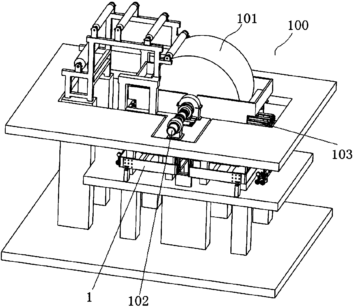
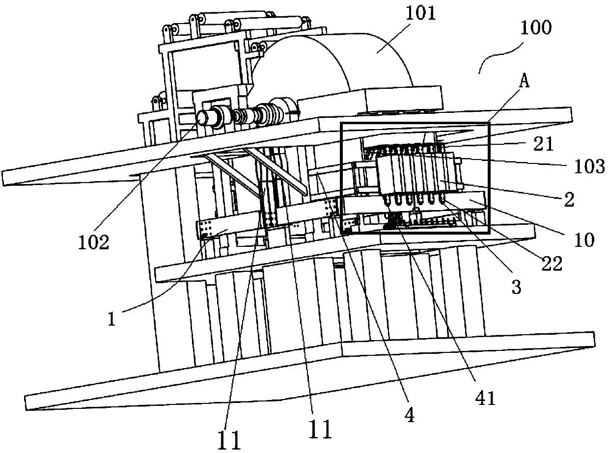
[0060] This embodiment provides an integrated structure of the power supply of the foil machine, such as Figure 2-4 As shown, there are two conductive bus bars 1, each conductive bus bar 1 is electrically connected to the two conductive columns 102 of the cathode roller 101 on the foil machine 100, and has a power connection section 10 , the power connection section 10 extends to a position corresponding to one of the anode plates 103, thereby forming an installation space between the power connection section 10 and the anode plate 103, and the installation space is suitable for installing at least one (there are 6 in this embodiment) power supply module 2 .

[0061] In the integrated structure of this embodiment, the conductive bus bar 1 has a power supply connection section 10, and the power supply connection section 10 is opposite to the anode plate 103 to form an installation space for installing the power supply module 2. Since the power supply module 2 is small in size,...

Embodiment 2

[0071] This implementation provides an integrated structure of the power supply of the foil machine, which is a deformation on the basis of Example 1. The difference is that in this embodiment, there is one conductive busbar, which is suitable for connecting with the two conductive busbars of the cathode roller on the foil machine. The column is electrically connected, and has two power supply connection sections, and the two power supply connection sections are respectively adapted to correspond to the two anode plates of the foil producing machine, thereby forming two installation spaces suitable for installing at least one power supply module.

Embodiment 3

[0073] This embodiment provides a copper foil production equipment, such as Figure 2-4 As shown, it is installed on a concrete structure, including: a foil machine 100, which has a cathode roller 101 and an anode plate 103, and the outer peripheral surface of the cathode roller 101 is opposite to the anode plate 103 to form a solution space; a conductive busbar 1, Each conductive bus bar 1 is electrically connected to two conductive columns 102 of the cathode roller 101, and has a power connection section 10, which extends to a position corresponding to one of the anode plates 103, so that An installation space is formed between the power connection section 10 and the anode plate 103; at least one power supply module 2 (six in this embodiment) is installed in the installation space, and the anode end 21 is connected to the anode plate 103 is electrically connected, and the cathode terminal 22 is electrically connected to the power connection section 10 .

[0074] In the copp...


PUM


Abstract

The invention provides a crude foil engine and power source integration structure and a copper foil production facility. The crude foil engine and power source integration structure comprises at least one conductive busbar, wherein the conductive busbars are suitable for being electrically connected with at least one conductive column on a cathode roller of a crude foil engine. Each conductive busbar comprises a power source connecting section. The power source connecting sections are suitable for being electrically connected with power source modules. The power source connecting sections stretch to the positions corresponding to at least one anode plate of the crude foil engine, and therefore an installation space which is suitable for installation of at least one power source module is formed between the power source connecting sections and the anode plates. By the adoption of the crude foil engine and power source integration structure, the power source modules are small in size and can be installed at the positions quite close to the anode plates, and therefore a large number of conductive busbars can be saved, and the whole facility is compact in structure and small in occupied space after installation is accomplished. In addition, after the conductive busbars are manufactured in a unified mode, the conductive busbars can be directly installed on the conductive columns of the cathode roller, after the conductive busbars and the cathode roller are fixedly connected, a user can accurately install the power source modules between the power source connecting sections and the anode plates, the installation process is simple, and the efficiency is high.

Description

technical field [0001] The invention relates to the technical field of equipment for producing copper foil by electrolysis, in particular to an integrated power supply structure of a foil raw machine and copper foil production equipment. Background technique [0002] Copper foil production equipment in the prior art generally includes a foil machine and a power supply (such as a high-frequency switching power supply). The foil machine includes an anode plate and a cathode roll. There is a solution space between the anode plate and the cathode roll. The foil machine provides direct current. When working, the copper sulfate solution is sent into the solution space between the anode plate and the cathode roller, and the foil machine is powered on for electrolysis, and the copper ions in the electrolysis area are gradually deposited on the surface of the cathode roller. Rotate, on the surface of the cathode roller that rotates out of the electrolysis area, an electrolytic coppe...

Claims


Application Information

Patent Timeline
Patent Type & Authority Patents(China)
IPC IPC(8): C25D1/04
CPCC25D1/04
Inventor 黄瑞炉
Owner 江西力源海纳科技股份有限公司
Why Eureka
Try Eureka