
Automatic pipeline inner wall sludge clearing device for hydraulic engineering

A water conservancy project, automatic cleaning technology, applied in the direction of water supply equipment, cleaning sewer pipes, waterway systems, etc., can solve the problems of difficult cleaning, short life and fragile, limited labor and power factors, etc., to save energy and avoid direct impact Effect

Inactive Publication Date: 2021-02-12
胡界鹏
View PDF8 Cites 2 Cited by
  • Summary
  • Abstract
  • Description
  • Claims
  • Application Information

AI Technical Summary

Problems solved by technology

[0006] In order to solve the above technical problems, the present invention provides an automatic desilting device for the inner wall of the pipeline used in water conservancy projects to solve the problem that the existing pipeline desilting device is placed inside the pipe during use, and the electric drive equipment has a short service life. Vulnerable, requires regular maintenance and replacement, difficult to maintain, difficult to clean according to the water flow, limited by labor and power factors

Method used


Image

  • Automatic pipeline inner wall sludge clearing device for hydraulic engineering
  • Automatic pipeline inner wall sludge clearing device for hydraulic engineering
  • Automatic pipeline inner wall sludge clearing device for hydraulic engineering

Examples


Embodiment

[0032] as attached figure 1 to attach Figure 7 Shown:

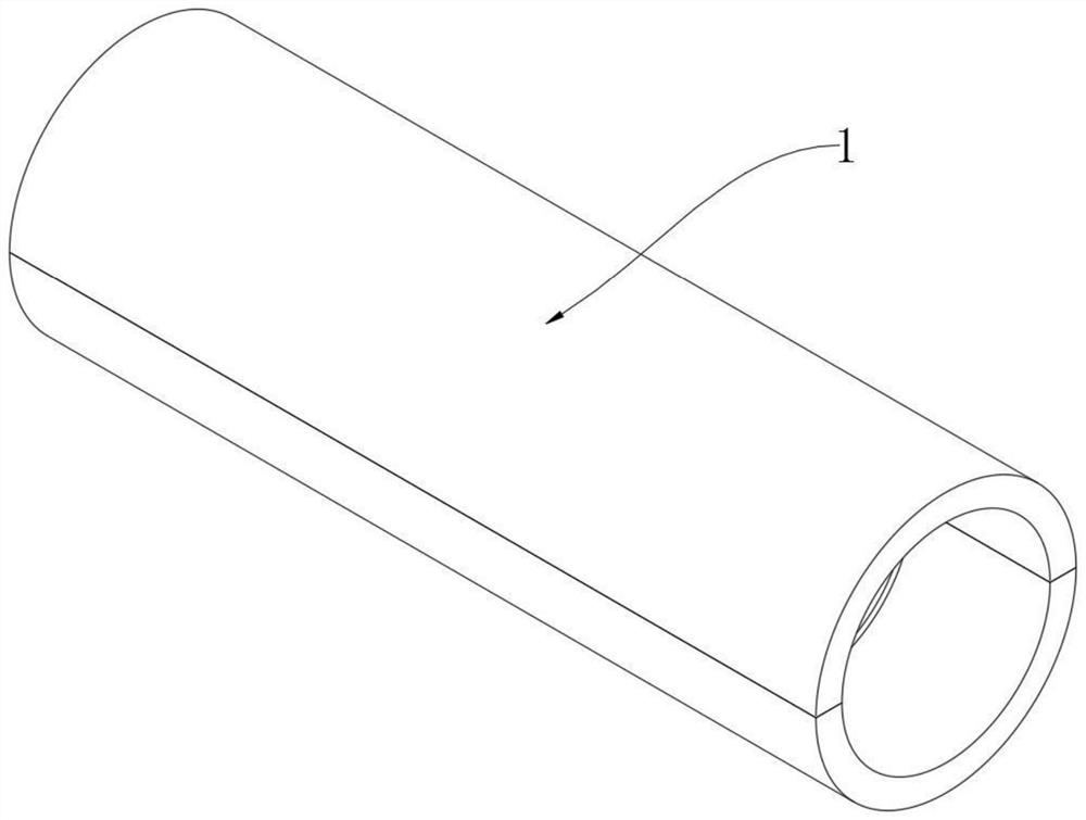
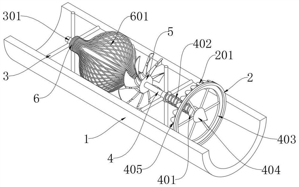
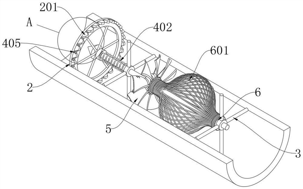
[0033] The invention provides an automatic desilting device for the inner wall of a pipeline used in water conservancy projects, which includes a water conservancy pipeline 1; a ring-shaped water inlet retaining ring 2 in a fixed inner cavity at the right end of the inner pipe of the water conservancy pipeline 1; and a water conservancy pipeline on the left side of the water inlet retaining ring 2 1. Two cross-shaped fixing frames 3 are installed at intervals in the inner tube; a frequency-moving mechanism 4 is slidably installed in the two fixing frames 3, and the right end of the frequency-moving mechanism 4 is tangent to the left end of the water inlet retaining ring 2; Mechanism 4 comprises baffle plate 401, spring 402, frequency moving wheel 403, water diversion cone 404 and dial 405, and baffle plate 401 is fixedly installed on the axle bar of frequency motion mechanism 4 right ends, and the frequency motion mecha...


PUM


Abstract

The invention provides an automatic pipeline inner wall sludge clearing device for hydraulic engineering, and relates to the technical field of water conservancy pipeline maintenance, and aims to solve the problems that an existing pipeline sludge clearing device is short in service life and easy to damage due to the fact that the existing pipeline sludge clearing device device is arranged in a tube in a using process, needs periodic maintenance and replacement, is difficult in maintenance, is difficult to clean according to water flow, and is limited by manual and electric factors. The automatic pipeline inner wall sludge clearing device comprises a water conservancy pipeline, wherein an annular water inlet baffle ring is arranged in a fixed inner cavity at the right end of the inner tubeof the water conservancy pipeline; and two cross-shaped fixed frames are mounted in the inner tube of the water conservancy pipeline on the left side of the water inlet baffle ring at intervals. At least 28 frequency moving blocks are uniformly and fixedly mounted on the left side of the annular wall of the water inlet baffle ring at intervals, sludge is prevented from being accumulated in the tube, the water conservancy pipeline at one end where the frequency moving blocks are located is a water outlet end, and the other end is a water inlet end, so that a frequency moving mechanism can be driven by water flow to rotate, and thus, the self-cleaning purpose is achieved, and energy is saved.

Description

technical field [0001] The invention relates to the technical field of maintenance of water conservancy pipelines, in particular to an automatic desilting device for inner walls of pipelines used in water conservancy projects. Background technique [0002] In water conservancy projects, all the pipes involved are large pipes with large diameters. Compared with municipal drainage pipes, the pipes are relatively large in diameter, and most of these pipes are used in the wild environment, lacking effective protection. Moreover, the liquid transported by the pipeline also has more impurities such as sand and soil in nature, and long-term use will cause more silt on the inner wall of the pipeline, which is difficult to clean. [0003] There are many existing pipeline desilting devices such as an automatic desilting device for the inner wall of a water conservancy pipeline in the patent application CN201810888914.4, which relates to the technical field of pipeline cleaning for wat...

Claims


Application Information

Patent Timeline
IPC IPC(8): F16L55/38E03F9/00F16L101/12
CPCF16L55/38E03F9/002F16L2101/12
Inventor 胡界鹏
Owner 胡界鹏
Learn More