Humidification mixer

A technology of mixer and air humidification, which is applied in air humidification system, heating method, lighting and heating equipment, etc. It can solve the problems of flow detection, follow-up environmental simulation cannot be carried out, long humidification distance and bulky volume, etc., to achieve humidification Good mixing effect, improved humidification effect, and small cross-sectional area of ​​the air duct

Pending Publication Date: 2021-02-12
BEIJING INST OF STRUCTURE & ENVIRONMENT ENG +1
View PDF0 Cites 1 Cited by
  • Summary
  • Abstract
  • Description
  • Claims
  • Application Information

AI Technical Summary

Problems solved by technology

At present, the existing industrial humidifiers either meet the requirements in size but the humidification capacity is small, or the humidification capacity meets the requirements but are bulky and require a long humidification distance.
Therefore, it is necessary to design a humidification mixer with strong humidification capacity, short humidification distance, small equipment footprint, good humidification and mixing effect, and can avoid water mist condensation caused by water vapor not completely absorbed by the air from impacting downstream equipment, causing flow detection , follow-up environment simulation, etc. cannot be carried out

Method used


Image

  • Humidification mixer
  • Humidification mixer
  • Humidification mixer

Examples


Embodiment 1

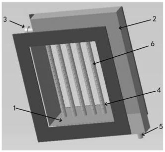
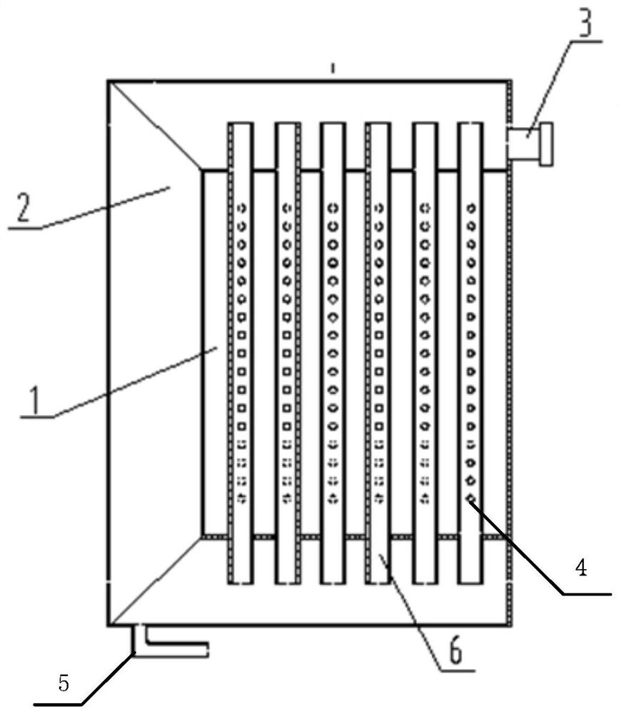
[0027] A kind of humidifying mixer disclosed in the embodiment of the application, such as figure 1 As shown, it includes the air intake pipe 1, which provides space for the air to enter the humidification mixer passage, and at the same time for the steam to mix with the air;

[0028] The air collecting pipe 2, which is partly welded to the air intake pipe 1 at the top, is a C-shaped through pipe with a hollow structure;

[0029] The steam inlet pipe 3 installed at the top end of the gas collecting pipe 2 is the channel for steam to enter the humidifying mixer;

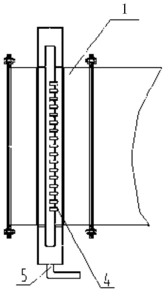
[0030] The humidifying rod 6 connected up and down with the gas collecting pipe 2, the humidifying rod 6 is a tubular structure, the upper and lower ends communicate with the gas collecting pipe 2, and the pipe body is welded somewhere in the air intake pipe 1, such as figure 2 shown;

[0031] There is a nozzle 4 on the humidifying rod 6, and the steam is ejected through the nozzle 4;

[0032] The condensation wat...

Embodiment 2

[0050] A working method of a humidifying mixer disclosed in an embodiment of the present application includes the following steps:

[0051] (1) The external saturated steam enters the humidifying mixer;

[0052] (2) The steam is ejected from the humidifying mixer and mixed with the air to humidify the air.

[0053] The specific implementation method of step (1) is: the external saturated steam enters the gas collecting pipe 2 through the steam inlet pipe 3, the steam on the upper part of the gas collecting pipe 2 enters the humidifying rod 6, and the steam that does not enter the humidifying rod 6 passes through the gas collecting pipe 2 to the humidifying rod 6. Part of the air intake pipe 1 is heated to reduce the condensation of this part of the steam, and at the same time, the remaining steam and part of the condensed water enter the condensed water pipe 5 through the air collecting pipe 2 and are discharged.

[0054] The specific implementation method of step (2) is: the...


PUM


Abstract

The invention provides a humidification mixer. A C-shaped air collecting pipe and multiple humidification rods with multiple nozzles are adopted. Under the condition that the humidification amount islarge, the humidification mixing distance is short, the humidification mixing effect is good, and the humidification mixer is fully mixed with air so as to meet the large-flow and short-distance humidification requirement. The humidification mixer is high in integration level, high in humidification capacity, short in humidification mixing distance, capable of comprehensively utilizing steam heatenergy, small in occupied area of equipment, small in sectional area of a needed air duct and capable of meeting the large-flow humidification requirement. According to the humidification mixer, the design of the multiple humidification rods with the multiple nozzles is adopted, so that the humidification uniformity can be improved, the humidification distance is shortened, the requirement for reducing the occupied space is met, and the humidification effect is improved.

Description

technical field [0001] The invention belongs to the technical field of humidification, and in particular relates to a humidification mixer. Background technique [0002] Humidity is a physical quantity that represents the degree of dryness of the atmosphere, and is one of the six most basic meteorological elements that reflect the natural climate. The humidity environment will have a major impact on people and things in it, and has great significance on human comfort and health, product quality, and product service life. Therefore, the climatic and environmental assessment for products generally includes separate or comprehensive assessments including humidity. At this time, it is necessary to construct an environment with a certain humidity. For example, when evaluating engine performance, it is necessary to truly simulate the temperature, humidity, and salt spray environment in which the engine is working. It is necessary to provide a high-humidity environment. The air wi...

Claims


Application Information

Patent Timeline
Patent Type & Authority Applications(China)
IPC IPC(8): F24F6/12F24F13/02F24F13/22
CPCF24F6/12F24F13/02F24F13/222
Inventor 刘玥马平昌高飞李红徐海博杨志鹏田义宏赖天明芮鹏李亚男李星
Owner BEIJING INST OF STRUCTURE & ENVIRONMENT ENG
Why Eureka
Try Eureka