
Detection and identification system and method based on computed tomography mode

A technology of tomography and identification methods, which is used in radio wave measurement systems, nuclear radiation exploration, measurement devices, etc.

Active Publication Date: 2021-02-12
THE SECOND ACAD OF CASIC
View PDF14 Cites 0 Cited by
  • Summary
  • Abstract
  • Description
  • Claims
  • Application Information

AI Technical Summary

Problems solved by technology

[0005] The purpose of the present invention is to provide a detection and identification system based on computerized tomography mode to solve the problem of taking into account the computerized tomography mode to construct effective detection and identification for aircraft

Method used


Image

  • Detection and identification system and method based on computed tomography mode
  • Detection and identification system and method based on computed tomography mode
  • Detection and identification system and method based on computed tomography mode

Examples


Embodiment 1

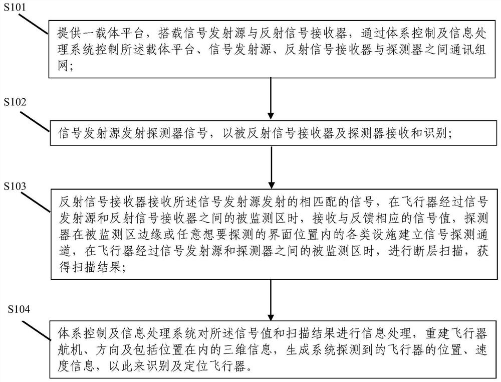
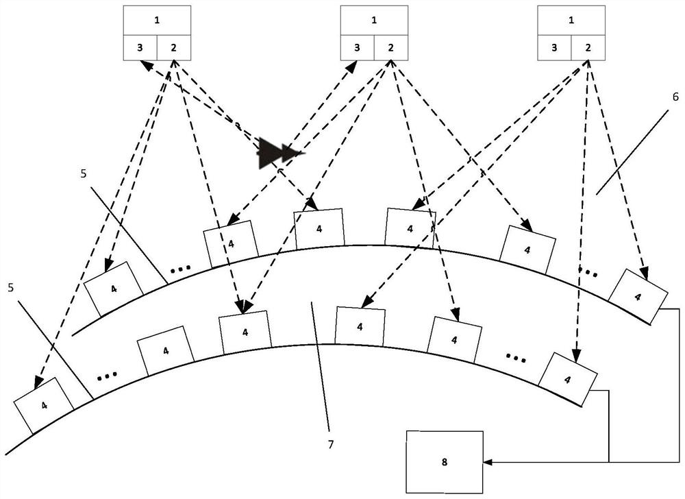
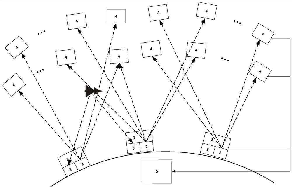
[0037] Please refer to Figure 1 to Figure 2 , a detection and recognition system based on computed tomography mode of the present invention, comprising:

[0038] The carrier platform is used to carry the signal transmitting source and the reflected signal receiver;

[0039] The signal transmitting source is used to transmit the detector signal to be received and identified by the reflected signal receiver and the detector;

[0040] The reflected signal receiver is used to receive the matching signal emitted by the signal transmitting source, and receive the signal value corresponding to the feedback when the aircraft passes through the monitored area between the signal transmitting source and the reflected signal receiver;

[0041] The detector is used to establish a signal detection channel at the edge of the monitored area or any desired detection interface position of various facilities. When the aircraft passes through the monitored area between the signal emission sourc...


PUM


Abstract

The invention discloses a detection and identification system and method based on a computed tomography mode. The system comprises a carrier platform, a signal transmitting source, a reflected signalreceiver, a detector and a system control and information processing system; the carrier platform is used for carrying the signal transmitting source and the reflected signal receiver; the signal emission source is used for emitting detector signals, so that the detector signals can be received and identified by the reflected signal receiver and the detector; the reflected signal receiver is usedfor receiving matched signals transmitted by the signal transmitting source, and receiving and feeding back a corresponding signal value when an aircraft passes through a monitored area between the signal transmitting source and the reflected signal receiver; the detector is used for establishing a signal detection channel at the edge of the monitored area or various facilities in any interface position to be detected, and carrying out tomography processing to obtain a scanning result; and the system control and information processing system is used for generating the position and speed information of the aircraft detected by a system so as to identify and position the aircraft. The method and method are simple to implement, realize the computed tomography mode, and construct effective detection and identification for the aircraft.

Description

technical field [0001] The invention belongs to the technical field of aircraft detection and identification, in particular to a detection and identification system and method based on computer tomography mode. Background technique [0002] The monitored area of ​​the aircraft refers to a specific area for centralized real-time monitoring and early warning of any possible security incidents that threaten the area based on safety needs, including the space area identification area, the airspace around core targets, and the airspace around important civilian targets. Any aircraft intruding into the monitored area may pose a threat to regional security. Early detection and identification of threatening targets in the monitored area is a necessary means to implement effective interception and ensure the safety of the monitored area. At present, the radar system is mainly used to monitor the monitored area of ​​the aircraft. The principle is that the radar transmitter emits elect...

Claims


Application Information

Patent Timeline
IPC IPC(8): G01S13/58G01B15/04G01N23/046G01V5/00
CPCG01S13/58G01B15/04G01V5/00G01N23/046Y02A90/30
Inventor 刘鹏浩秦秀波赵宏鸣马喆毛磊
Owner THE SECOND ACAD OF CASIC
Learn More