Fluorescent structure, optical device, warning device and control method of warning device

An optical device and warning device technology, applied in the field of optical components, can solve the problems of reduced traffic safety warning function, optimized adjustment of excitation light direction, decreased warning effect, etc. Effect

Pending Publication Date: 2021-02-12
单正建 +1
View PDF0 Cites 1 Cited by
  • Summary
  • Abstract
  • Description
  • Claims
  • Application Information

AI Technical Summary

Problems solved by technology

[0003] However, no matter what kind of fluorescent structures are currently used in the field of traffic warning, they all simply use sunlight to excite fluorescence, and sunlight depends on climate characteristics, so with fog, haze, rain, snow, cloudy In the natural climate, the intensity of irradiation on the traffic warning fluorescent material will naturally decrease, so the ability to excite fluorescence will naturally decrease, so the warning effect will drop significantly; in addition, in the traffic environment, the warning usually has a specific direction, while the existing traffic fluorescent application, there is no optimal adjustment to the direction of the excitation light to help traffic participants observe as much as possible (it is excitation in the form of scattering and diffusion), so after the above single factor or the superposition of both, the traffic safety warning function is greatly improved. The reduction has also become one of the important causes of road traffic accidents and secondary accidents today. However, the standard setting of European standards and national standards in this field just ignores the above problems

Method used


Image

  • Fluorescent structure, optical device, warning device and control method of warning device
  • Fluorescent structure, optical device, warning device and control method of warning device
  • Fluorescent structure, optical device, warning device and control method of warning device

Examples


Embodiment Construction

[0060] Hereinafter, exemplary embodiments according to the present disclosure will be described in detail with reference to the accompanying drawings. Apparently, the described embodiments are only some of the embodiments of the present disclosure, rather than all the embodiments of the present disclosure, and it should be understood that the present disclosure is not limited by the exemplary embodiments described here.

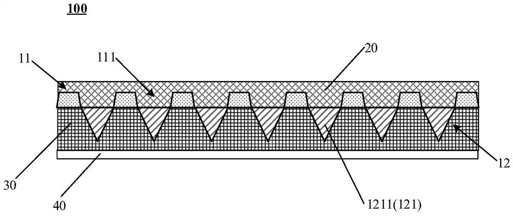
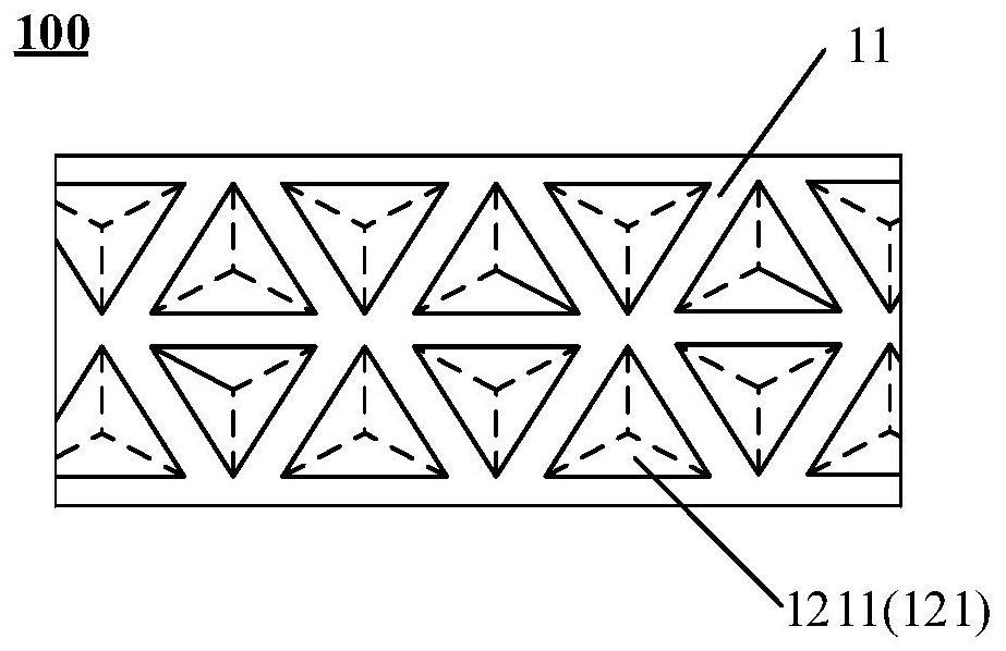
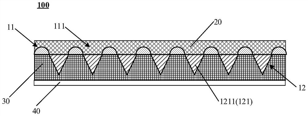
[0061] figure 1 Shown is a schematic structural view of the fluorescent structure provided by an embodiment of the present disclosure. Such as figure 1 As shown, the fluorescent structure 100 provided by the embodiment of the present disclosure includes a fluorescent layer 11 and a reflective layer stacked with the fluorescent layer 11 . Specifically, the phosphor layer 11 includes a plurality of phosphor grooves 111, and the plurality of phosphor grooves 111 are along the stacking direction of the phosphor layer 11 (such as figure 1 The vertical direction...


PUM


Abstract

The invention provides a fluorescent structure, an optical device, a warning device and a control method of the warning device, and relates to the technical field of optical elements. The fluorescentstructure comprises a fluorescent layer comprising a plurality of fluorescent grooves, wherein the plurality of fluorescent grooves penetrate through the fluorescent layer along the stacking directionof the fluorescent layer; and a reflecting layer which is overlapped with the fluorescent layer, wherein the reflecting layer is used for conducting light reflection operation based on the fluorescent grooves. According to the invention, the fluorescence excitation effect can be optimized, the warning capability can be enhanced, and the reflection effect can be enhanced. Particularly, when the fluorescent structure provided by the invention is applied to triangular warning boards, road cones and the like for traffic warning, the warning effect on drivers and passengers is further improved, and the probability of secondary accidents is further reduced. Especially in foggy days, sand and dust and other particle climate astronomical phenomena, an existing triangular warning board is extremely poor in yellow light reflection effect, and the triangular warning board adopting the fluorescent structure provided by the invention has no influence on the yellow light reflection effect.

Description

technical field [0001] The present disclosure relates to the technical field of optical components, and in particular to a fluorescent structure, an optical device, a warning device and a control method for the warning device. Background technique [0002] In the prior art, usually on the warning frame or warning device (such as the triangle warning frame applied to the car, the traffic cone, the warning pile), the plastic containing the fluorescent material is used or the surface is laid with a fluorescent material, and the fluorescence is excited under the sunlight. Use longer-wavelength light (such as red light) to improve the visual significance of the warning frame or warning device, and enhance its warning effect from the visual level. [0003] However, no matter what kind of fluorescent structures are currently used in the field of traffic warning, they all simply use sunlight to excite fluorescence, and sunlight depends on climate characteristics, so with fog, haze, ...

Claims


Application Information

Patent Timeline
Patent Type & Authority Applications(China)
IPC IPC(8): G09F13/16G09F13/20G09F13/22G02B5/122
CPCF21V5/02F21V2200/00F21Y2115/10F21V7/28F21V9/32G08B5/38G08G1/09G09F13/005G09F13/22G09F25/00G09F2013/222
Inventor 单正建
Owner 单正建
Why Eureka
Try Eureka