Robot-assisted fracture reduction path planning method and planning system and robot

A path planning and robot technology, applied in the field of surgical robots, can solve the problems of insufficient precision and safety, easy collision, insufficient or excessive rotation, etc., to achieve the effect of reducing secondary injuries, fast and accurate reset, and reducing collisions

Active Publication Date: 2021-02-19
毕建平
View PDF8 Cites 2 Cited by
  • Summary
  • Abstract
  • Description
  • Claims
  • Application Information

AI Technical Summary

Problems solved by technology

However, it is impossible for the distal and proximal fracture fragments to automatically avoid collisions in a fixed state. Since the limbs are a closed space composed of skin, muscles, etc., collisions are easy to occur during the path planning process. Secondly, it is easy to appear Insufficient or excessive axis adjustment, insufficient or excessive rotation, etc., make the path planning work repeated, the robot also moves repeatedly, and it is impossible to control the surgical robot to quickly and accurately perform fracture reduction
In the prior art, when robot-assisted surgery is performed for reduction, the large-scale pulling of the distal end and the collision between the distal end of the fracture and surrounding tissues are prone to medical accidents, and there are still deficiencies in accuracy and safety.

Method used


Image

  • Robot-assisted fracture reduction path planning method and planning system and robot
  • Robot-assisted fracture reduction path planning method and planning system and robot
  • Robot-assisted fracture reduction path planning method and planning system and robot

Examples


Embodiment 1

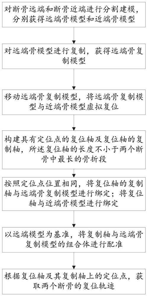
[0050] In the technical solutions disclosed in one or more embodiments, such as Figure 1-11 As shown, a robot fracture reduction path planning method is used to realize the reduction of two broken bones, including the following steps:

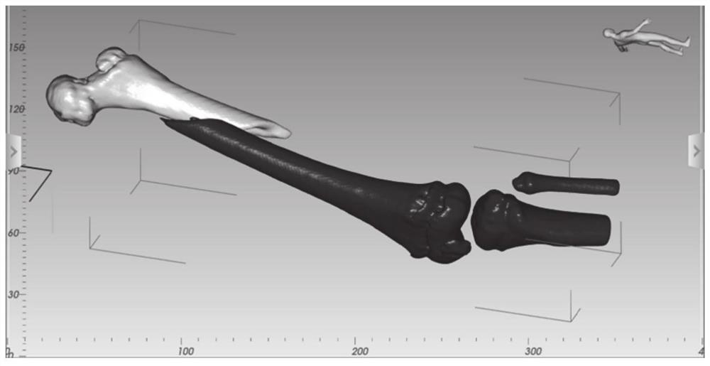
[0051] Step 1. Obtain a CT scan image of the fractured bone, segment and model the distal end of the broken bone and the proximal end of the broken bone, and obtain the distal bone model and the proximal bone model respectively;

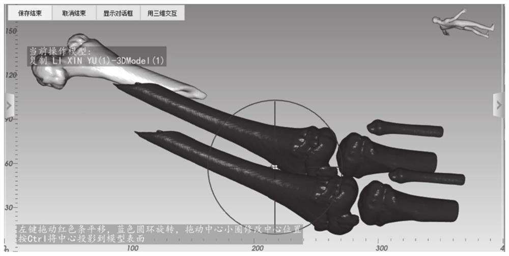
[0052] Step 2, duplicating the distal bone model to obtain the distal bone duplication model;

[0053] Step 3, move the distal bone replica model, and virtual reset the distal bone replica model and the proximal bone model;

[0054] Step 4, constructing a reduction axis with an anchor point and a copy axis of the reduction axis, the length of the reduction axis is not less than the longest fracture segment among the two broken bones;

[0055] Step 5. According to the same position of the anchor point, bind the copy...

Embodiment 2

[0090] This embodiment provides a robot fracture reduction path planning method, which is used to realize the reduction of multiple broken bones. Each segment of the distal bone model is connected in sequence according to the proximal bone model. When one of the distal bones and the proximal bone are reset As the current proximal bone and the next distal bone are reset, the robot fracture reduction path planning method described in Embodiment 1 is used for the reduction of the current proximal bone and the distal bone.

[0091] Specific steps are as follows:

[0092] (1) take the proximal end bone as the current proximal end bone, and use the broken bone adjacent to it as the current distal end bone, and use the method described in Embodiment 1 to carry out path planning;

[0093] (2) the current distal bone is reset;

[0094] (3) The combination of the current proximal bone and the current distal bone is used as the current proximal bone, and the adjacent broken bone is used...

Embodiment 3

[0098] Based on the method described in Embodiment 1, this embodiment provides a robot fracture reduction path planning system, including:

[0099] Segmentation modeling module: configured to obtain a CT scan image of a fractured bone, segment and model the distal end and the proximal end of the fractured bone, and obtain a distal bone model and a proximal bone model respectively;

[0100] Model replication module: configured to replicate the distal bone model to obtain a distal bone replication model;

[0101] Virtual reduction module: configured to move the distal bone replication model, virtual reset the distal bone replication model and the proximal bone model to obtain a combined reset model;

[0102] A reduction axis generating module: configured to construct a reduction axis having an anchor point and a copy axis of the reduction axis, the length of the reduction axis is not less than the longest fracture segment among the two broken bones;

[0103] Binding module: con...


PUM


Abstract

The invention provides a robot-assisted fracture reduction path planning method and planning system and a robot. The method comprises the following steps of performing segmentation modeling to obtaina distal-end bone model and a proximal-end bone model; duplicating the distal-end bone model to obtain a distal-end bone duplicating model; performing virtual reduction on the distal-end bone duplicating model and the proximal-end bone model to obtain a reduction combination model; constructing a reduction axis with a positioning point and a duplicating axis of the reduction axis; binding a duplicating axis of the reduction axis with the distal-end bone duplicating model; binding the reduction axis with the proximal-end bone model; registering a combination of the duplicating axis and the distal-end bone duplicating model by taking the distal-end model as a reference; and according to the positioning points on the reduction axis and the duplicating axis of the reduction axis, obtaining reduction tracks of two broken bones. By arranging the reduction axis with the positioning point, matching between the distal-end model and the proximal-end model is converted into matching of the reduction axis, the reduction track more suitable for clinical application can be obtained, rapid and accurate reduction can be achieved, collision in the reduction process is avoided, and secondary injuries to a patient are reduced.

Description

technical field [0001] The present disclosure relates to the technical field related to surgical robots, and in particular, relates to a robot fracture reduction path planning method, a planning system and a robot. Background technique [0002] The statements in this section merely provide background information related to the present disclosure and may not necessarily constitute prior art. [0003] Fracture reduction has always been a thorny problem in the fracture treatment process, especially under closed conditions, it is almost impossible to achieve the ideal reduction position. With the development of robotic technology, research on robot-assisted fracture reduction has been carried out at home and abroad. Correct and reasonable preoperative reduction path planning is the premise to ensure the safety of surgery, and it is of great significance to improve the accuracy of surgery and reduce the surgical injury of patients. [0004] The inventors found that using roboti...

Claims


Application Information

Patent Timeline
Patent Type & Authority Applications(China)
IPC IPC(8): A61B34/10A61B34/30A61B34/00
CPCA61B34/10A61B34/30A61B34/71A61B2034/105A61B2034/108A61B2034/104
Inventor 毕建平马平
Owner 毕建平
Why Eureka
Try Eureka