Positioning welding base of electronic component

An electronic component, positioning welding technology, applied in welding equipment, auxiliary welding equipment, welding/cutting auxiliary equipment, etc., can solve the problems of inconvenient manual welding operation, high labor intensity, low efficiency, etc. The effect of efficiency

Inactive Publication Date: 2021-02-19
程艳云
View PDF0 Cites 1 Cited by
  • Summary
  • Abstract
  • Description
  • Claims
  • Application Information

AI Technical Summary

Problems solved by technology

[0002] like figure 1 As shown, it is a schematic diagram of the structure of straw hat lamp beads, sensors and other similar structural electrical components. In some working conditions, the wiring pins of these components need to be bent and then welded with the wire harness. Traditionally, manual bending is mainly used. , and then manually weld them together, because the pin spacing of straw hat electronic components is small, manual welding operation is inconvenient, inefficient, and labor-intensive, therefore, it is necessary to provide an automatic welding method that can realize similar components and wiring harnesses device of

Method used


Image

  • Positioning welding base of electronic component
  • Positioning welding base of electronic component
  • Positioning welding base of electronic component

Examples


Embodiment Construction

[0037] In order to make the purpose and advantages of the present application clearer, the present application will be specifically described below in conjunction with the embodiments. It should be understood that the following words are only used to describe one or several specific implementation modes of the application, and do not strictly limit the scope of protection specifically requested by the application. The features in the examples can be combined with each other.

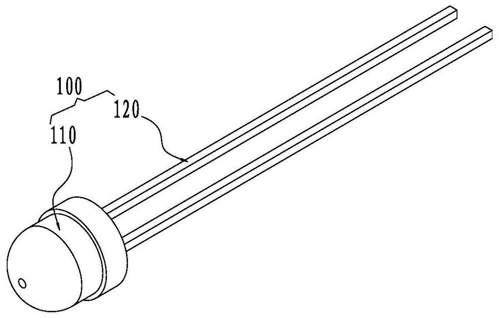
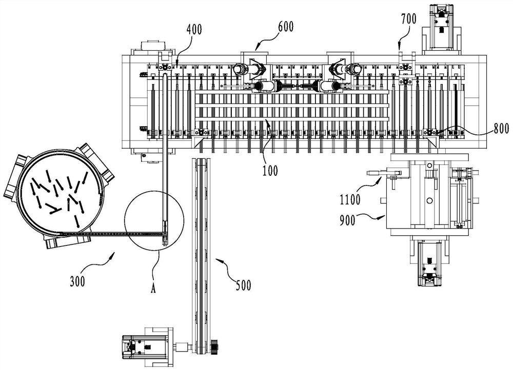
[0038] refer to Figure 1 to Figure 16 , the embodiment of the present application provides an electronic component and wire harness assembly equipment, including a welding base 400, the welding base 400 is used for positioning the wire harness 200 to be assembled and the electronic component 100 to be assembled, wherein the wire harness 200 includes The A line 210, the B line 220, the welding base 400 makes the line ends of the A line 210 and the B line 220 overlap with the ends of the two pins 120 of ...


PUM


Abstract

The invention relates to a positioning welding base of an electronic component, which comprises a welding base body, a C positioning part and a D positioning part, wherein the C positioning part and the D positioning part are arranged on the upper surface of the welding base body and are used for respectively positioning the component and a wire harness; and the positioning part C and the positioning part D are oppositely arranged on the welding base, so that two pins of the component and wire cores at the end parts of a wire A and a wire B forming the wire harness are arranged in a lap jointmanner. By adopting the positioning welding base provided by the invention, the positioning efficiency can be effectively improved, and subsequent welding is facilitated; and the labor intensity can be reduced, and the labor workload is reduced.

Description

technical field [0001] The invention relates to the field of assembly of electronic components, in particular to a positioning welding base of electronic components. Background technique [0002] Such as figure 1 As shown, it is a schematic diagram of the structure of straw hat lamp beads, sensors and other similar structural electrical components. In some working conditions, the wiring pins of these components need to be bent and then welded with the wire harness. Traditionally, manual bending is mainly used. , and then manually weld them together, because the pin spacing of straw hat electronic components is small, manual welding operation is inconvenient, inefficient, and labor-intensive, therefore, it is necessary to provide an automatic welding method that can realize similar components and wiring harnesses device of. Contents of the invention [0003] The purpose of the present invention is to provide a positioning welding base for electronic components, which can ...

Claims


Application Information

Patent Timeline
IPC IPC(8): B23K37/04B23K101/36
CPCB23K37/0443B23K2101/36
Inventor 程艳云
Owner 程艳云
Why Eureka
Try Eureka