Transmission mechanism of numerical control vertical machining center

A transmission mechanism, CNC vertical technology, applied in metal processing machinery parts, metal processing, metal processing equipment and other directions, can solve the problem of power equipment and transmission mechanism can not be quickly separated to stop power transmission, power equipment damage, short circuit and other problems, to achieve Easy to assemble the hole and avoid the effect of load phenomenon

Inactive Publication Date: 2021-02-19
汉刚机械(南京)有限公司
View PDF5 Cites 2 Cited by
  • Summary
  • Abstract
  • Description
  • Claims
  • Application Information

AI Technical Summary

Problems solved by technology

[0003] The transmission mechanism of the existing CNC vertical machining centers is mostly connected between the shafts to achieve power transmission. One end of the shaft is connected to the power equipment, and then the power equipment drives the shaft to rotate. Its power is transmitted, so as to drive the components assembled on the shaft to work, so as to ensure the operation of the equipment. The transmission mechanism of the existing CNC vertical machining center often occurs when the equipment encounters a large obstacle during work. The load of the power equipment is too large, and the power equipment and the transmission mechanism cannot be quickly separated to stop the power transmission, resulting in damage or short circuit of the power equipment. For this reason, we propose a transmission mechanism for CNC vertical machining centers

Method used


Image

  • Transmission mechanism of numerical control vertical machining center
  • Transmission mechanism of numerical control vertical machining center
  • Transmission mechanism of numerical control vertical machining center

Examples


Embodiment 1

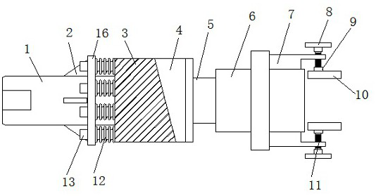
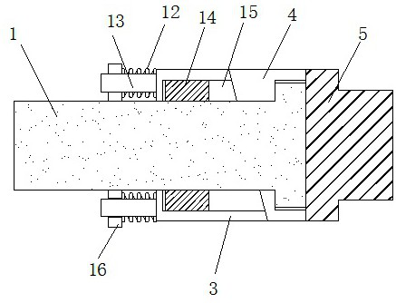
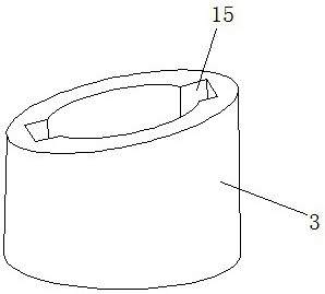
[0024] see Figure 1 to Figure 4 , the present invention provides a technical solution: a transmission mechanism of a numerically controlled vertical machining center, including a transmission shaft 1, and one end of the transmission shaft 1 is provided with a first connecting block 3 and a second connecting block 4, through the first designed The slopes of the first connecting block 3 and the second connecting block 4 are squeezed and contacted with each other, thereby ensuring synchronous rotation and realizing power transmission. At the same time, the two are assembled separately. The inclined surface produces an effect, provides thrust to the two connecting blocks, thereby realizing disengagement, stopping power transmission, and effectively avoiding the load phenomenon of the power source. The adjacent surfaces of the first connecting block 3 and the second connecting block 4 are provided with equal inclined The other end of the first connecting block 3 is provided with a...

Embodiment 2

[0028] see Figure 1 to Figure 5 , the present invention provides a technical solution: a transmission mechanism of a numerically controlled vertical machining center, including a transmission shaft 1, and one end of the transmission shaft 1 is provided with a first connecting block 3 and a second connecting block 4, through the first designed The slopes of the first connecting block 3 and the second connecting block 4 are squeezed and contacted with each other, thereby ensuring synchronous rotation and realizing power transmission. At the same time, the two are assembled separately. The inclined surface produces an effect, provides thrust to the two connecting blocks, thereby realizing disengagement, stopping power transmission, and effectively avoiding the load phenomenon of the power source. The adjacent surfaces of the first connecting block 3 and the second connecting block 4 are provided with equal inclined The other end of the first connecting block 3 is provided with a...


PUM


Abstract

The invention discloses a transmission mechanism of a numerical control vertical machining center. The transmission mechanism comprises a transmission shaft, one end of the transmission shaft is sleeved with a first connecting block and a second connecting block, the adjacent faces of one ends of the first connecting block and the second connecting block are provided with inclined faces with the same inclination, the other end of the first connecting block is provided with a mounting disc, the outer wall of the transmission shaft is sleeved with the mounting disc, and a spring is arranged between the mounting disc and the first connecting block. According to the transmission mechanism of the numerical control vertical machining center, through the designed first connecting block and the second connecting block, the inclined faces of the first connecting block and the second connecting block are in mutual extrusion contact, so that synchronous rotation can be ensured, power transmissionis realized, meanwhile, the first connecting block and the second connecting block are separately assembled, when the first connecting block and the second connecting block are subjected to excessiveresistance, the inclined faces of the first connecting block and the second connecting block generate an acting effect to provide thrust for the two connecting blocks, so that separation is realized,power transmission is stopped, and the load phenomenon of a power source is effectively avoided.

Description

technical field [0001] The invention belongs to the technical field of numerically controlled vertical machining centers, and in particular relates to a transmission mechanism of a numerically controlled vertical machining center. Background technique [0002] The CNC vertical machining center is a highly automated multifunctional CNC machine tool with a tool magazine and an automatic tool changer. After the workpiece is clamped once on the machining center, the digital control system can control the machine tool to automatically select and process according to different processes. Change the tool, automatically change the machine tool spindle speed, feed rate and the movement track of the tool relative to the workpiece and other auxiliary functions, complete the multi-process processing on several surfaces of the workpiece in sequence, and have a variety of tool changing or tool selection functions, so that the production The efficiency is greatly improved. When the CNC ver...

Claims


Application Information

Patent Timeline
Patent Type & Authority Applications(China)
IPC IPC(8): B23Q5/58B23Q11/00F16D43/21
CPCB23Q5/58B23Q11/00F16D43/218
Inventor 郭奕廷
Owner 汉刚机械(南京)有限公司
Why Eureka
Try Eureka