Redundancy control method of automatic driving system, automatic driving system, automobile, controller and computer readable storage medium

A redundant control and automatic driving technology, which is applied in the field of automobiles, controllers and computer readable storage media, and automatic driving systems, can solve hardware or software failures and low calculation errors, high complexity of multi-sensor perception fusion systems, lane Line error recognition, etc.

Active Publication Date: 2021-02-19
CHONGQING CHANGAN AUTOMOBILE CO LTD
View PDF25 Cites 9 Cited by
  • Summary
  • Abstract
  • Description
  • Claims
  • Application Information

AI Technical Summary

Problems solved by technology

The front-view camera, which is the main sensor for lane keeping, is generally based on the deep learning system, or the combination of deep learning system and classic image recognition technology for the recognition of lane lines. Influenced by factors such as lane markings, the wrong recognition of the lane line, especially the curvature of the lane centerline
Moreover, the multi-sensor perception fusion system is highly complex, and the possibility of hardware or software failures and calculation errors (such as random flipping of some register states) is not low.
This has led to safety problems easily caused by failures and errors in the system during the lane keeping process of medium / high-level autonomous vehicles; distracted by the system, so this security problem is more deadly

Method used


Image

  • Redundancy control method of automatic driving system, automatic driving system, automobile, controller and computer readable storage medium
  • Redundancy control method of automatic driving system, automatic driving system, automobile, controller and computer readable storage medium
  • Redundancy control method of automatic driving system, automatic driving system, automobile, controller and computer readable storage medium

Examples


Embodiment Construction

[0221]First, it should be noted that each calculation formula in the embodiment of the present invention uses the center of gravity of the vehicle as the origin of the coordinates, and the direction is defined by SAE. In the vehicle coordinate system, the horizontal axis is the y axis (the right side is positive), and the vertical axis is the x axis (the front side is positive). The yaw rate is positive clockwise, and the steering wheel angle is positive left and negative right. The change of the vehicle coordinate system does not affect the physical meaning of the calculation results of this plan and the implementation of the plan.

[0222]The embodiment of the present invention provides a redundant control method applied to a high-level automatic driving system (level 4 or 5) and a middle-level automatic driving system (level 2.5 or 3).

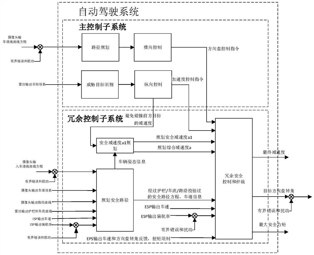
[0223]For high-level autonomous driving systems and mid-level autonomous driving systems, both includefigure 1 The main control subsystem and redundan...


PUM


Abstract

The invention relates to a redundancy control method of an automatic driving system, the automatic driving system, an automobile, a controller and a computer readable storage medium, which are used for keeping running along the center line of a lane when the automatic driving system has a fault and the fault does not exceed tolerance. The method comprises the steps of: when an automatic driving function is activated, fitting a safe path equation enabling a vehicle to run along the center line of a lane according to information collected by a forward-looking camera and a radar, and determiningthe lane width of the lane where the vehicle is located currently; according to the coefficient of the safe path equation and the determined lane width, determining a current specific offset area of the vehicle; determining the current fault level of a main control subsystem according to the offset area where the vehicle is located and whether the vehicle activates the function of a first redundant safety control module in the previous control period or not; and activating the redundancy control function of the corresponding level according to the current fault level of the main control subsystem, and controlling the vehicle according to the redundancy control function of the corresponding level.

Description

Technical field[0001]The invention is used in the field of automobile automatic driving control and safety control, and specifically is a redundant control of an automatic driving system to maintain and decelerate the emergency lane of the vehicle when the sensor / main control subsystem / actuator is faulty and the fault is bounded. Method, automatic driving system, automobile, controller and computer readable storage medium.Background technique[0002]The safety of a mid / high level (above 2.5 level) autopilot system depends on the correct output of each sensor. The front-view camera, which is the main sensor for lane keeping, is generally based on the deep learning system or the combination of deep learning system and classic image recognition technology. It is prone to lighting, alternating light and dark, road surface water reflection, and road slope. The lane markings and other factors affect the wrong recognition of the lane line, especially the curvature of the lane centerline. In ...

Claims


Application Information

Patent Timeline
Patent Type & Authority Applications(China)
IPC IPC(8): B60W40/00B60W50/00B60W60/00
CPCB60W40/00B60W50/00B60W60/00B60W2050/0002
Inventor 李锐任传兵王黎萌单玉梅
Owner CHONGQING CHANGAN AUTOMOBILE CO LTD
Why Eureka
Try Eureka