Eureka AIR delivers breakthrough ideas for toughest innovation challenges, trusted by R&D personnel around the world.

Connecting device and method for connecting joint of buckling restrained brace and existing concrete beam

A technology of concrete beams and buckling restraint, applied in the direction of building maintenance, construction, building structure, etc., can solve the problems of loose connection, poor reliability connection, affecting the use function of buildings, etc., and achieve the effect of improving reliable connection

Pending Publication Date: 2021-02-19
上海市建工设计研究总院有限公司
View PDF0 Cites 0 Cited by
  • Summary
  • Abstract
  • Description
  • Claims
  • Application Information

AI Technical Summary

Problems solved by technology

Its disadvantage is that when the beam or column cross-section increases to a large area, it not only affects the use function of the building, but also the project cost is relatively high, and the connection nodes between the ordinary support and the original concrete components will cause great damage to the original structure, making the construction difficult
Another method in the prior art is to connect existing concrete beams with buckling-restrained supports to resist earthquake forces. The disadvantage is that the strength of existing concrete beams is not high, and the joints are easily damaged, and the buckling restraints are immediately yielded. When the support is vibrated by axial force, its connection with the existing concrete beam is prone to loosening or even detachment, resulting in poor reliability of the connection between the buckling restrained support and the existing concrete beam

Method used


Image

  • Connecting device and method for connecting joint of buckling restrained brace and existing concrete beam
  • Connecting device and method for connecting joint of buckling restrained brace and existing concrete beam
  • Connecting device and method for connecting joint of buckling restrained brace and existing concrete beam

Examples


Embodiment 1

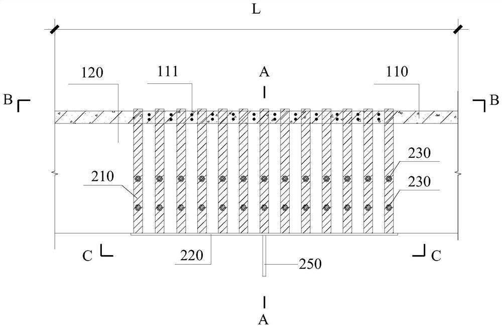
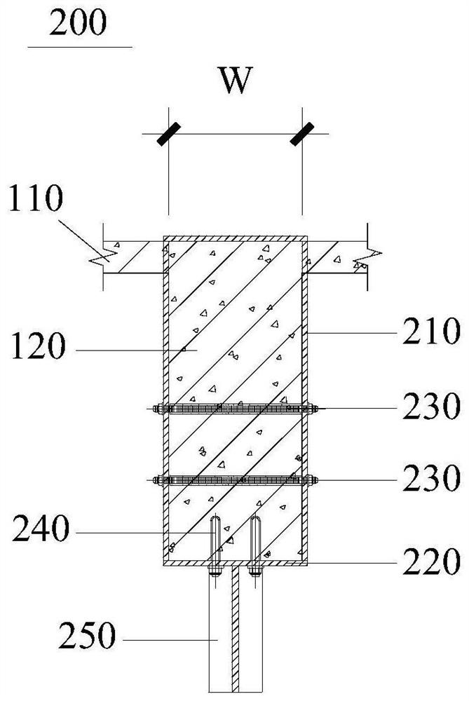
[0054] Please refer to Figure 1 to Figure 6 Embodiment 1 of the present invention provides a connection device 200 for connecting nodes between buckling constrained supports and existing concrete beams, including U-shaped steel plates 210 , tension bolts 230 , back cover plates 220 , anchor bolts 240 and gusset plates 250 .

[0055] Please refer to Figure 1 to Figure 3 , Figure 5 to Figure 6 , wherein there are several U-shaped steel plates 210 arranged along the length L direction of the existing concrete beam 120 and the existing floor 110 on it; each of the U-shaped steel plates 210 includes a transverse steel plate 211, and Two vertical steel plates 212 vertically connected downwards at both ends of the two ends; the horizontal steel plate 211 is placed on the existing floor 110, and the two vertical steel plates 212 avoid the reinforcing bars 111 of the existing floor 110 and penetrate the existing floor 110 Extending downward along both sides of the existing concret...

Embodiment 2

[0064] Embodiment 2 of the present invention provides a construction method for the connection device 200 of the buckling-constrained support and the connection node of the existing concrete beam according to the above-mentioned embodiment 1, including:

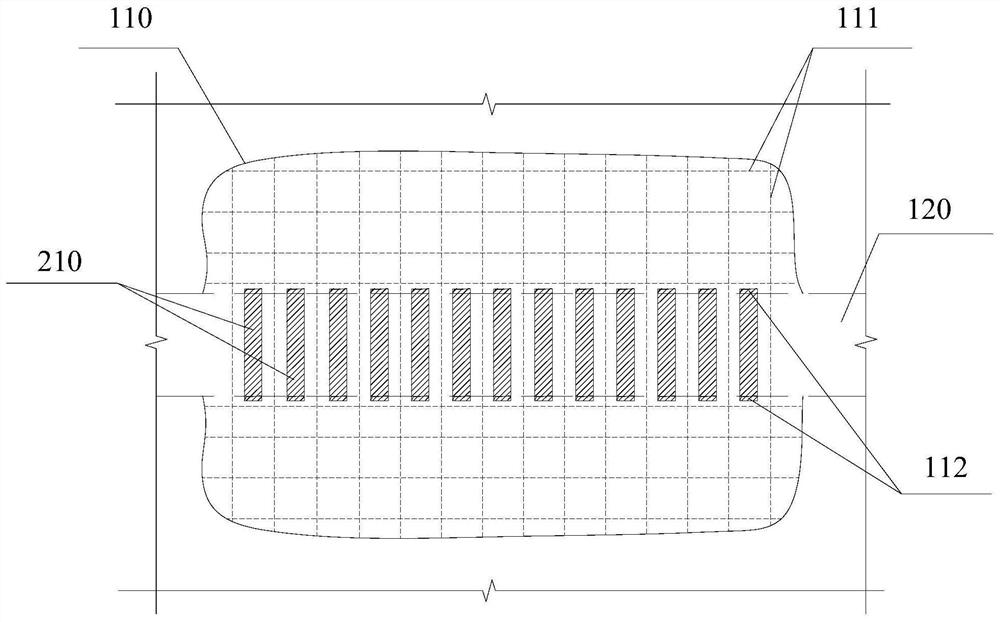
[0065] Step 501, please refer to image 3 and Figure 5 , on the connecting node of the existing concrete beam 120, avoid the steel bar 111 of the existing floor 110 and open the hole 112 on the existing floor 110. Of course, before opening the opening 112 , it may include measuring and setting out, and locating the plane positions of the existing floor 110 and the existing concrete beam 120 . And it includes measuring the position of the reinforcing bar 111 of the existing floor 110 .

[0066] Step 502, please refer to Figure 5 , Drilling construction bolt holes 121 on existing concrete beams 120 .

[0067] Step 503, please refer to figure 2 , install the U-shaped steel plate 210 through the hole 112, so that the hori...

Embodiment 3

[0073] Embodiment 3 of the present invention provides a method for connecting a buckling restrained support to an existing concrete beam connection node, including:

[0074] Step 601, please refer to Figure 7 to Figure 8 The connection device 200 is constructed according to the construction method of the connection device of the buckling-constrained support and the connection node of the existing concrete beam in the second embodiment above.

[0075] Step 602, please refer to Figure 7 and Figure 8 , install the adapter assembly 400 on the buckling restraint support 300 .

[0076] Step 603, please refer to Figure 7 and Figure 8 , welding the adapter assembly 400 on the back cover plate 220 and the gusset plate 250 of the connection device 200 .

[0077] In step 604, the connection device 200 and the adapter assembly 400 may be subjected to fire prevention and anticorrosion treatment.

[0078] The above embodiments of the present invention provide the connection devic...


PUM


Abstract

The invention discloses a connecting device and method for a connecting joint of a buckling restrained brace and an existing concrete beam. The device comprises a plurality of U-shaped steel plates, split bolts, a bottom sealing plate, anchoring bolts and a joint plate, wherein the U-shaped steel plates are arranged in the length direction of the existing concrete beam and an existing floor on theexisting concrete beam; the split bolts are used for fixing the U-shaped steel plates to the existing concrete beam; the bottom sealing plate is arranged on the lower surface of the existing concretebeam and welded to the U-shaped steel plates; the anchoring bolts are used for anchoring the bottom sealing plate to the existing concrete beam; and the joint plate is perpendicularly arranged on thelower surface of the bottom sealing plate. By adoption of the connecting device and method, reliable connection between the existing concrete beam and the buckling restrained brace can be improved.

Description

technical field [0001] The invention relates to the technical field of construction engineering, in particular to a connection device and method for connecting nodes between buckling constrained supports and existing concrete beams. Background technique [0002] In the reinforcement and reconstruction project of the upper structure of the existing building, the traditional method is to increase the column section, increase the beam section or increase the support between ordinary columns to dissipate energy and resist earthquake force. Its disadvantage is that when the beam or column cross-section increases to a large area, it not only affects the use function of the building, but also the project cost is relatively high, and the connection nodes between the ordinary support and the original concrete components will cause great damage to the original structure, making the construction difficult . Another method in the prior art is to connect existing concrete beams with buc...

Claims


Application Information

Patent Timeline
Patent Type & Authority Applications(China)
IPC IPC(8): E04G23/02
CPCE04G23/0218
Inventor 廖利敏李静张珏
Owner 上海市建工设计研究总院有限公司
Why Eureka
Eureka Blog
Learn More