Data acquisition method and device for industrial equipment

A technology of industrial equipment and data acquisition, which is applied in the direction of measuring devices, mechanical equipment, and components of the damping parts of the measuring device. It can solve the problems of parts production impact, data accuracy cannot be guaranteed, and labor waste, etc., to ensure safety , Promote the effect of anti-dumping effect

Inactive Publication Date: 2021-02-19
胡艳荣
View PDF4 Cites 1 Cited by
  • Summary
  • Abstract
  • Description
  • Claims
  • Application Information

AI Technical Summary

Problems solved by technology

[0003] However, in large-scale manufacturing workshops, the data collection of industrial equipment is still completed by manual recording, reporting and sorting, which not only causes a waste of labor, but also cannot gu

Method used


Image

  • Data acquisition method and device for industrial equipment
  • Data acquisition method and device for industrial equipment
  • Data acquisition method and device for industrial equipment

Examples


Embodiment 1

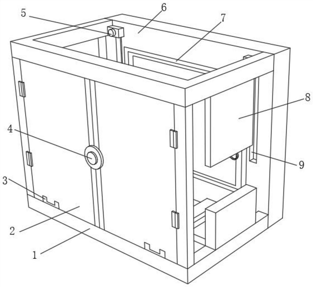
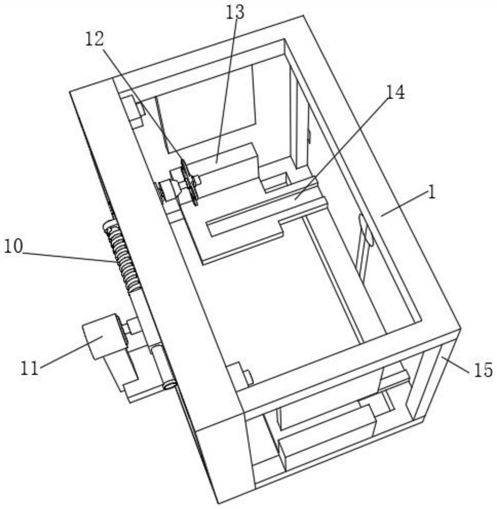
[0036] A data acquisition device for industrial equipment, such as Figure 1-5As shown, it includes two U-shaped fixed frames 1, the outer walls of the opposite sides of the two U-shaped fixed frames 1 are respectively fixed with support rods 15 by bolts, and the outer walls of the ends of the two U-shaped fixed frames 1 are respectively connected by bolts. The same mounting plate 6 is fixed, and the outer walls of the mounting plate 6 close to the inner sides of the two U-shaped fixing frames 1 have rectangular holes, and the inner walls of the sides of the rectangular holes are bonded with rubber sealing strips 7, and the mounting plate 6 is close to the rectangular holes. There are chute 9 on both sides of the outer wall, and the inner walls of the two chute 9 are slidably connected with buffers 5, and the outer walls on both sides of the bottom of one U fixing frame 1 are respectively fixed with baffles 8 by bolts, and the other U The outer walls on both sides of the top o...

Embodiment 2

[0042] A method for collecting industrial equipment data, comprising the following steps:

[0043] S1: Fix various data collectors in each installation hole 28 and the end of the installation cylinder 25 through clips;

[0044] S2: Open the limit door 2, introduce the industrial equipment to the two L-shaped backing plates 13 through the two guide grooves 14, close the limit door 2, so that the two limit doors 2 are snapped into the two guide holes 3 fixed;

[0045] S3: When one side of the industrial equipment touches the rubber support column 30 due to the driving force, the pushing force will be weakened by the tightening of the return spring 32, which plays a role in protecting the industrial equipment;

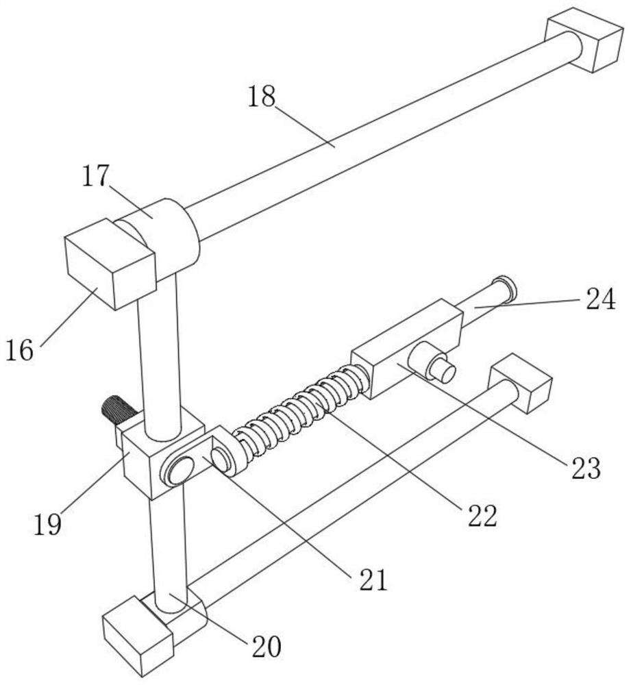
[0046] S4: By starting the motor 11, the motor 11 drives the connecting shaft to rotate, and the rotating connecting shaft drives the sliding sleeve 23 to slide on the limit rod 24, and at the same time compresses the telescopic spring 22, and makes the L-shaped connecti...


PUM


Abstract

The invention discloses a data acquisition method and device for industrial equipment, and relates to the technical field of data acquisition for industrial equipment. The invention aims to solve theefficiency problem of data acquisition for the industrial equipment. The device specifically comprises U-shaped fixing frames, wherein support rods are fixed to the outer walls of the opposite sides of the two U-shaped fixing frames through bolts separately; a same mounting plate is fixed to the outer walls of the end parts of the two U-shaped fixing frames through the bolts separately, and a rectangular hole is formed in the outer wall, close to the inner sides of the two U-shaped fixing frames, of the mounting plate; a rubber sealing strip is bonded to the inner wall of the side of the rectangular hole; sliding grooves are formed in the outer walls of two sides, close to the rectangular hole, of the mounting plate; a buffer is connected to the inner wall of each of two sliding grooves ina sliding manner; and baffles are fixed to the outer walls of two sides of the bottom of one U-shaped fixing frame through the bolts separately. A data acquisition unit of an acquisition and installation mechanism is driven to acquire various data of the industrial equipment, so that the data acquisition efficiency of the industrial equipment is effectively improved, and meanwhile, errors causedby manual work are also reduced.

Description

technical field [0001] The invention relates to the technical field of data collection of industrial equipment, in particular to a method and device for data collection of industrial equipment. Background technique [0002] Industrial equipment refers to industrial production equipment and various machine tools, such as lathes, milling machines, grinders, planers and other machines. With the evolution of large-scale industrial production, the importance of monitoring technology on production equipment is gradually recognized by people, and whether it is production management, parts management, equipment management, order management, or enterprise decision-making, it is inseparable from the on-site production situation. timely grasp. [0003] However, in large-scale manufacturing workshops, the data collection of industrial equipment is still completed by manual recording, reporting and sorting, which not only causes a waste of labor, but also cannot guarantee the accuracy o...

Claims


Application Information

Patent Timeline
IPC IPC(8): F16M11/04F16M11/06F16M11/18F16M11/22F16M1/00F16M7/00F16F15/08G01D11/30G01D11/10
CPCF16M11/04F16M11/06F16M11/18F16M11/22F16M1/00F16M7/00F16F15/08G01D11/30G01D11/10
Inventor 胡艳荣
Owner 胡艳荣
Why Eureka
Try Eureka