
Zoom lens and security camera device

A zoom lens and drive device technology, applied in the focus device, installation, optics, etc., can solve the problems of the zoom lens such as low zoom speed, susceptibility to electromagnetic interference noise, poor wear resistance, etc., and achieve fast zoom speed, low power consumption, wear-free effect

Pending Publication Date: 2021-02-19
UNION OPTECH
View PDF0 Cites 0 Cited by
  • Summary
  • Abstract
  • Description
  • Claims
  • Application Information

AI Technical Summary

Problems solved by technology

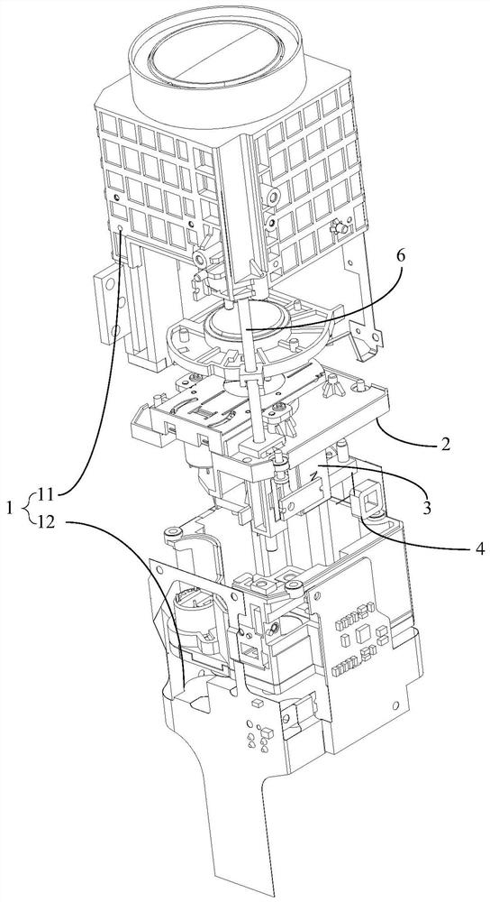
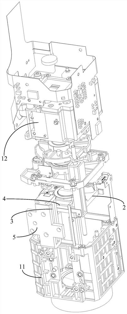
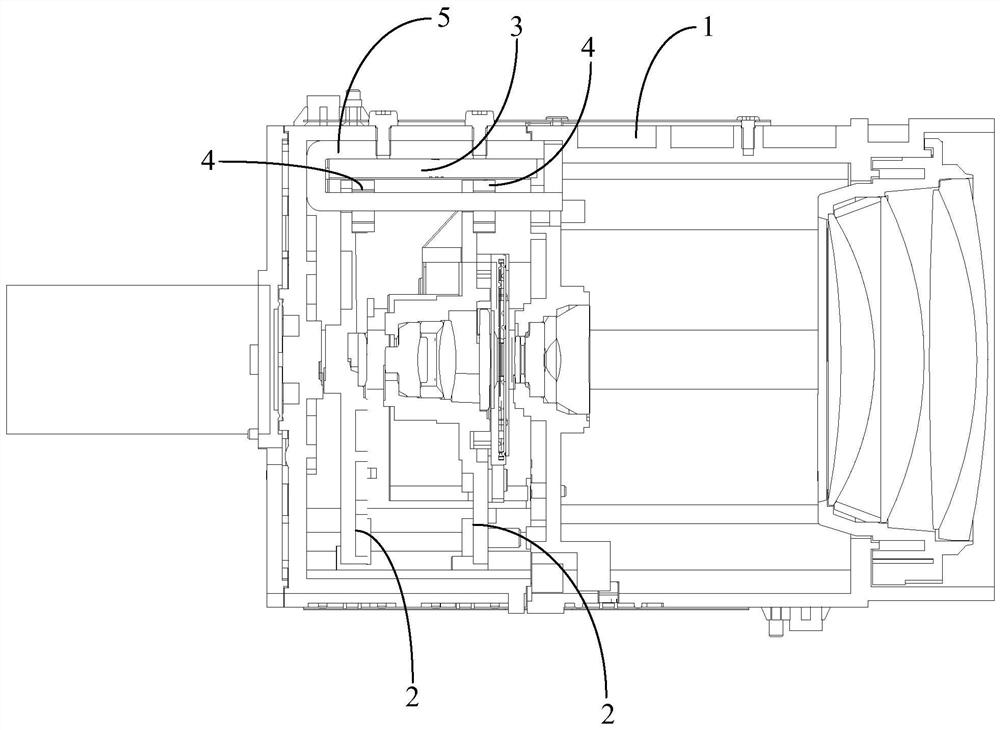
[0003] The main purpose of the present invention is to provide a zoom lens and a security camera device, aiming at solving the problems of low zoom speed, high power consumption, susceptibility to electromagnetic interference and high noise, and poor wear resistance of the zoom lens in the related art

Method used


Image

  • Zoom lens and security camera device
  • Zoom lens and security camera device
  • Zoom lens and security camera device

Examples


Embodiment Construction

[0027] The following will clearly and completely describe the technical solutions in the embodiments of the present invention with reference to the accompanying drawings in the embodiments of the present invention. Obviously, the described embodiments are only part of the embodiments of the present invention, not all of them. Based on the embodiments of the present invention, all other embodiments obtained by persons of ordinary skill in the art without creative efforts fall within the protection scope of the present invention.

[0028] It should be noted that all directional indications (such as up, down, left, right, front, back...) in the embodiments of the present invention are only used to explain the relationship between the components in a certain posture (as shown in the accompanying drawings). Relative positional relationship, movement conditions, etc., if the specific posture changes, the directional indication will also change accordingly.

[0029] In addition, the ...


PUM


Abstract

The present invention discloses a zoom lens and a security camera device. The zoom lens comprises: a lens barrel, a moving carrier and a moving lens, wherein the lens barrel is provided with an innercavity, the moving carrier is movably arranged in the inner cavity, the moving carrier can slide in a reciprocating mode in the length direction of the lens barrel, and the moving lens is contained inthe inner cavity and arranged on the moving carrier; and a driving device which comprises a magnet and a power-on coil, one of the magnet and the power-on coil is arranged on the moving carrier, theother one of the magnet and the power-on coil is arranged on the inner wall of the inner cavity, and the power-on coil and the magnet are oppositely arranged. By utilizing the principle that the electrified coil generates interaction force with the magnetic field generated by the magnet after being electrified to generate the magnetic field, relative movement is generated between the electrified coil and the magnet, and the electrified coil or the magnet drives the moving carrier for bearing the moving lens to move, so that zooming is realized, and the zoom lens has the effects of high zoomingspeed, no abrasion, low noise and low power consumption.

Description

technical field [0001] The invention relates to the technical field of security equipment, in particular to a zoom lens and a security camera device using the zoom lens. Background technique [0002] With the rapid development of technology, zoom lenses have been widely used in security equipment, and stepping motors are widely used in automatic zooming of zoom lenses. In related technologies, the stepping motor drives the lens to move in the lens barrel to achieve zooming. However, the stepping motor drive method has the disadvantages of low zoom speed, high power consumption, high susceptibility to electromagnetic interference and noise, and poor wear resistance. Contents of the invention [0003] The main purpose of the present invention is to provide a zoom lens and a security camera device, aiming to solve the problems of low zoom speed, high power consumption, susceptibility to electromagnetic interference, high noise, and poor wear resistance of the zoom lens in the...

Claims


Application Information

Patent Timeline
IPC IPC(8): G02B7/09G03B13/36
CPCG02B7/09G03B13/36
Inventor 赵媚娇孔旭东李昆王浩邱盛平龚俊强
Owner UNION OPTECH
Learn More