Jig cover plate disassembling and assembling mechanism of chip assembling feeding and discharging machine

A technology of loading and unloading, cover plate, applied in electrical components, semiconductor/solid-state device manufacturing, circuits, etc., can solve problems such as imperfect function, cover plate tilt, low stability, etc., to save operation time, increase reliability, The effect of improving efficiency

Pending Publication Date: 2021-02-19
苏州茂特斯自动化设备有限公司
View PDF0 Cites 2 Cited by
  • Summary
  • Abstract
  • Description
  • Claims
  • Application Information

AI Technical Summary

Problems solved by technology

[0003] Most of the existing chip fixture cover plate disassembly and assembly mechanisms are mechanisms that need to be manually disassembled and assembled. Although there are a few mechanisms that automatically disassemble the cover plate on the market, most of these mechanisms do not have enough functions. Perfect, there will be situations where the jig cover cannot be removed, and the use effect is not ideal, which greatly reduces the efficiency of chip assembly
[0004] At the same time, due to the fact that the existing chip jig cover plate disassembly mechanism is inlaid with multiple magnets on the jig bottom plate, the cover plate will be tilted when taking the cover plate, which will cause the cover plate to be closed after disassembly. At this time, the cover plate cannot be accurately placed into the positioning pins on the bottom plate of the fixture, and the stability is low, which is also one of the problems that reduce the overall efficiency of the chip automatic cutting equipment

Method used


Image

  • Jig cover plate disassembling and assembling mechanism of chip assembling feeding and discharging machine
  • Jig cover plate disassembling and assembling mechanism of chip assembling feeding and discharging machine

Examples


Embodiment Construction

[0024] The present invention will be described in detail below with reference to the accompanying drawings and in combination with embodiments. The descriptions here are used to provide a further understanding of the present invention and constitute a part of the application. The exemplary embodiments of the present invention and their descriptions are used to explain the present invention and do not constitute improper limitations to the present invention.

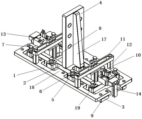
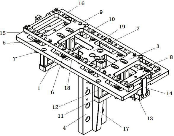
[0025] see Figure 1-2 As shown, a jig cover disassembly mechanism of a chip assembly loading and unloading machine includes a hollowed out thimble mounting plate 1 in the middle, and a hollow structure of the thimble mounting plate 1 is provided with a The linear bearing mounting plate 2, the bottom of the thimble mounting plate 1 is provided with a cover plate laminating plate 3 parallel to the thimble mounting plate 1; the upper surface of the linear bearing mounting plate 2 is provided with a vertical mechanism instal...


PUM


Abstract

The invention discloses a jig cover plate disassembling and assembling mechanism of a chip assembly feeding and discharging machine, which comprises an ejector pin mounting plate. A linear bearing mounting plate is arranged in the ejector pin mounting plate, a cover plate fitting plate is arranged below the ejector pin mounting plate, and the linear bearing mounting plate is connected with the cover plate fitting plate through a linear bearing and a guide shaft. The cover plate fitting plate is connected with the ejector pin mounting plate through an ejector pin cylinder and a connecting block. A mechanism mounting plate is arranged in the middle of the linear bearing mounting plate, cover plate clamping jaws are arranged at the left end and the right end of the linear bearing mounting plate through clamping jaw opening and closing air cylinders, and ejector pins are arranged at the bottom of a frame of the ejector pin mounting plate and penetrate through ejector pin through holes in the cover plate attaching plate. And a magnet is arranged at the bottom of the frame of the cover plate fitting plate through an iron mounting groove. The type and number of the magnets can be quicklyreplaced, the suction efficiency of the cover plate is greatly improved, the risk that the cover plate falls off can be avoided through the cover plate clamping jaws on the two sides, reliability is improved, the cover plate can be smoothly separated from the mechanism through the ejector pins at the bottom, and the position of the cover plate is guaranteed.

Description

technical field [0001] The invention belongs to the field of chip assembly, and in particular relates to a jig cover disassembly mechanism of a chip assembly loading and unloading machine, which is used for jig cover disassembly, cover transportation and jig positioning. Background technique [0002] In the semiconductor industry, in order to speed up production, the chip assembly and loading machine is usually equipped with a jig cover disassembly mechanism, so as to complete the work of disassembling and closing the jig cover before and after chip assembly. [0003] Most of the existing chip fixture cover plate disassembly and assembly mechanisms are mechanisms that need to be manually disassembled and assembled. Although there are a few mechanisms that automatically disassemble the cover plate on the market, most of these mechanisms do not have enough functions. If it is perfect, there will be situations where the jig cover cannot be removed, and the use effect is not ide...

Claims


Application Information

Patent Timeline
Patent Type & Authority Applications(China)
IPC IPC(8): H01L21/67
CPCH01L21/67011H01L21/67092H01L21/67121H01L21/67126
Inventor 李立红温定进
Owner 苏州茂特斯自动化设备有限公司
Why Eureka
Try Eureka