Thin-plate frame structure linear ultrasonic motor stator with empennages and excitation method thereof

A linear ultrasonic motor, frame structure technology, applied in piezoelectric effect/electrostrictive or magnetostrictive motors, generators/motors, electrical components, etc., can solve the limitation of length or width, and the vibrator structure is not easy to miniaturize , bending deformation of bending nodes, etc., to achieve large driving force and driving speed, without affecting the vibration effect, and the effect of frequency degeneracy

Active Publication Date: 2021-02-19
HARBIN INST OF TECH
View PDF19 Cites 3 Cited by
  • Summary
  • Abstract
  • Description
  • Claims
  • Application Information

AI Technical Summary

Problems solved by technology

[0006] Ultrasonic motors are suitable for miniaturization. In summary, the stators (oscillators) of the above-mentioned linear ultrasonic motors have some difficulties in miniaturization. , are limited in the length or width direction; second, there are certain difficulties in fixing the vibrator. Generally, the fixed position is selected at the node of the first-order longitudinal vibration and the second-order bending vibration. However, the bending vibration node has bending deformation, which weakens the bending vibration

Method used


Image

  • Thin-plate frame structure linear ultrasonic motor stator with empennages and excitation method thereof
  • Thin-plate frame structure linear ultrasonic motor stator with empennages and excitation method thereof
  • Thin-plate frame structure linear ultrasonic motor stator with empennages and excitation method thereof

Examples


Embodiment 1

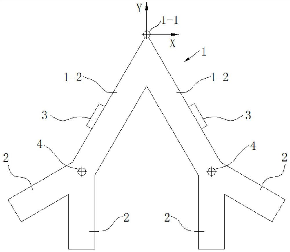
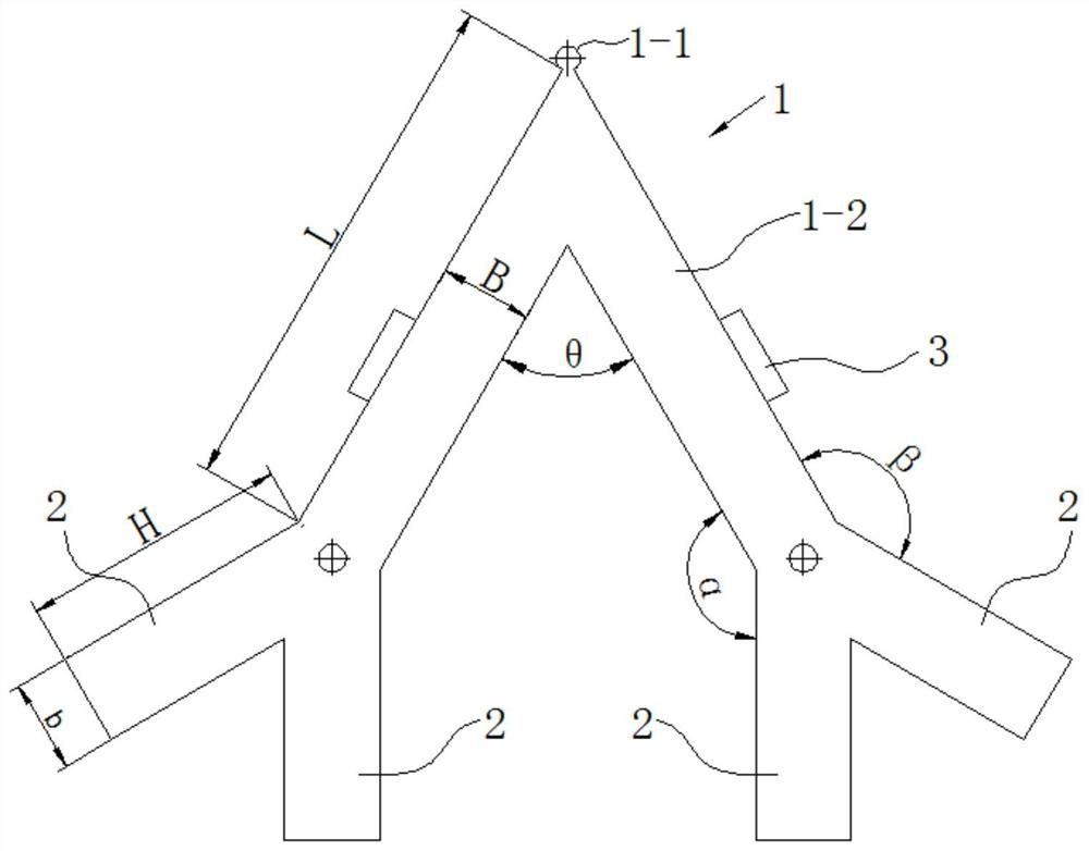
[0060] Embodiment 1, the quantity of the thin-plate empennage 2 of the present embodiment is 4, and two thin-plate empennages 2 are respectively arranged on both sides 1-2 of the V-shaped frame 1, as Figure 6 As shown, the side length L=11.5mm of the V-shaped frame 1, the width B=2mm, and the included angle θ=60°. The mounting hole 4 is circular, located at the junction of the V-shaped side and the empennage, and fixed with a pin. The thin-plate empennage 2 is located at the end of the V-shaped side, and the structural size of the thin-plate empennage is completely symmetrical, and the two thin-plate empennages 2 are arranged symmetrically with the center line of the mounting hole. The length H=5.7mm of single thin-plate tail 2, width b=2mm, the thickness of both sides 1-2 of V-shaped frame 1 and thin-plate tail 2 are 0.5-2mm, the thin-plate tail 2 of the outside and V-shaped frame side angle 150 °, the angle between the inner tail fin and the V-shaped side is 150°, and two p...

Embodiment 2

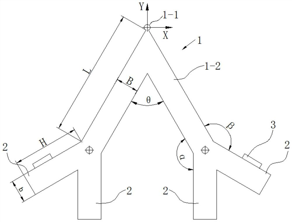
[0061] Embodiment 2. In this embodiment, on the basis of the V-shaped frame 1 described in Embodiment 1, the arrangement position and included angle of the thin-plate empennage 2 are adjusted. The difference from Embodiment 1 is that α=180°, β=90°, θ=90°, get as Figure 9 As shown in the stator structure, designing a circular drive at the driving point 1-1 is sufficient to increase the amplitude, and the symmetrical mode is as Figure 10 As shown, the antisymmetric mode is as Figure 11 As shown, the two modes are orthogonally superimposed at the driving point to form an elliptical motion and drive the guide rail to move.

Embodiment 3

[0062] Embodiment 3, on the basis of the V-shaped frame described in Embodiment 1, the arrangement position and the included angle of the thin plate empennage 2 are adjusted. The difference from Embodiment 1 is that α=90°, β=180°, and θ=90 °, get as Figure 12 As shown in the stator structure, designing a circular drive at the driving point 1-1 is sufficient to increase the amplitude, and the symmetrical mode is as Figure 13 As shown, the antisymmetric mode is as Figure 14 As shown, the two modes are orthogonally superimposed at the driving point to form an elliptical motion and drive the guide rail to move.


PUM


Abstract

The invention discloses a thin-plate frame structure linear ultrasonic motor stator with empennages and an excitation method thereof. The main body of a stator is V-shaped, the main body of the statoris a frame formed by thin plates, the tail parts of the two sides of the V-shaped frame are provided with thin plate empennages, mounting holes are formed in the connecting parts of the V-shaped frame and the thin plate empennages, and piezoelectric ceramic pieces are mounted on the thick side surface of the V-shaped frame or the thick side surfaces of the thin plate empennages. The excitation method comprises the steps that piezoelectric ceramic pieces are installed on the thick side surfaces of the two sides of the V-shaped frame, or piezoelectric ceramic pieces are installed on the thick side surfaces of the thin-plate empennages, alternating current signals with the phase difference of 90 degrees are applied to the piezoelectric ceramic pieces on the V-shaped frame or the thin-plate empennages, and vibration in the Y-axis direction and vibration in the X-axis direction with the phase difference of 90 degrees can be excited on a driving point, so that elliptical motion is synthesized at the driving point. If the phase difference of excitation signals of the two corresponding piezoelectric ceramic pieces is changed, the elliptical motion of the driving point can be opposite in rotation direction, and the stator can be driven in two directions. The stator is compact in structure and reliable in vibration effect.

Description

technical field [0001] The invention relates to an ultrasonic motor stator, in particular to a thin plate frame structure linear ultrasonic motor stator with tail fins and an excitation method thereof. Background technique [0002] The ultrasonic motor is a motor that uses the inverse piezoelectric effect of piezoelectric materials to convert electrical energy into mechanical energy of the stator, excites an elliptical motion at the drive foot end of the stator, and then converts the motor into rotation or linear motion of the moving parts through contact friction. Compared with traditional electromagnetic motors, ultrasonic motors have many unique advantages such as low-speed high-power output, no noise, flexible and compact structure, high energy density, and easy miniaturization. [0003] The stator is the core component of the ultrasonic motor. For a linear ultrasonic motor, the stator structure is mainly flat, and there are also a few slender cylindrical structures. Th...

Claims


Application Information

Patent Timeline
Patent Type & Authority Applications(China)
IPC IPC(8): H02N2/12H02N2/14
CPCH02N2/003H02N2/12H02N2/14
Inventor 曲建俊刘晨东曲华杰张磊
Owner HARBIN INST OF TECH
Why Eureka
Try Eureka