
Fertilizing and soil loosening device for tea tree planting
A tea tree and vertical rod technology, applied in the direction of shovels, plows, springs/shock absorbers, etc., can solve problems such as damage, high vibration frequency, and damaged tea tree growth, so as to improve the scope of application, protect products, and reduce the probability of damage Effect
- Summary
- Abstract
- Description
- Claims
- Application Information
AI Technical Summary
Problems solved by technology
Method used
Image

Examples
Embodiment 1
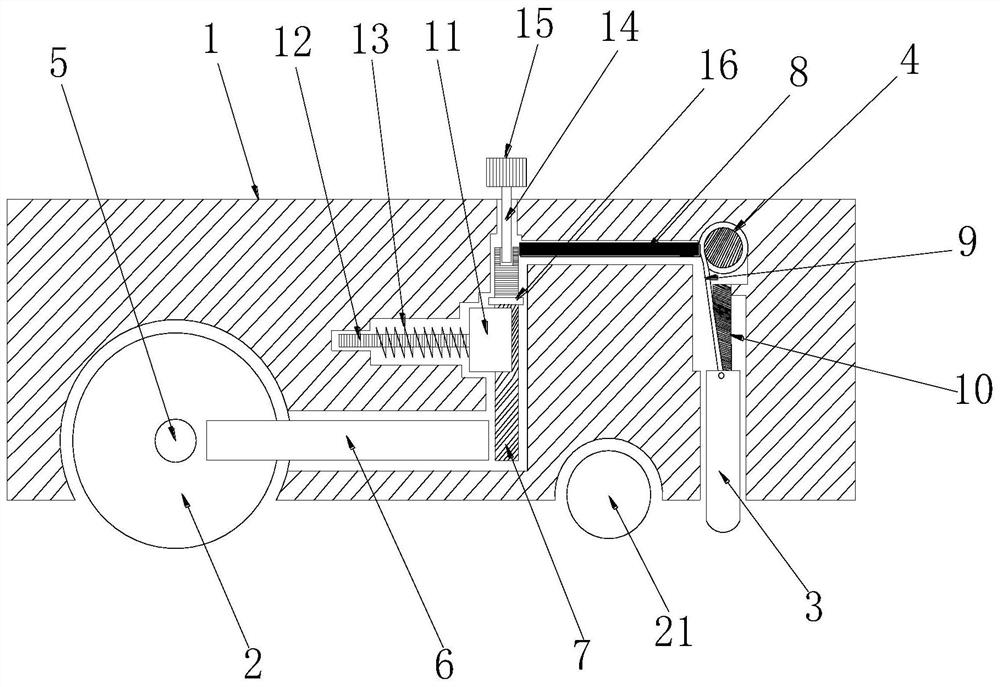
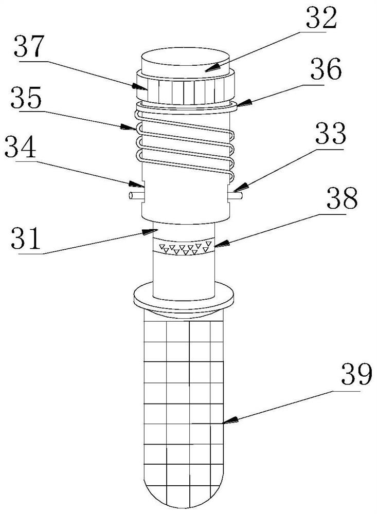
[0031] refer to figure 1 , figure 2 , image 3 , Figure 6 , the present embodiment provides a tea tree planting, fertilizing and loosening device, including a device body 1, a main wheel 2 and a secondary wheel 21, a transmission mechanism, a rewinding mechanism equipped with a clockwork spring, a plurality of loosening teeth 3 and recovery mechanism.
[0032] Both the main wheel 2 and the auxiliary wheel 21 are installed on the device body 1 .
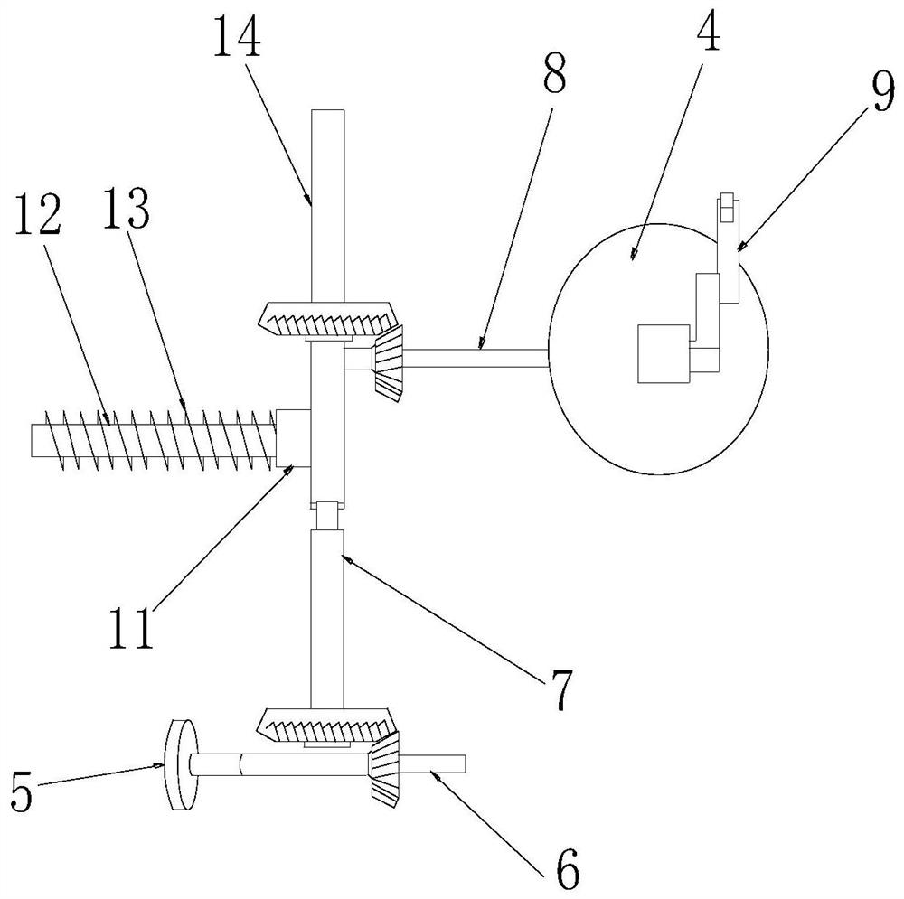
[0033] The transmission mechanism includes a first horizontal bar 6, a first vertical bar 7, and a second horizontal bar 8; both ends of the first horizontal bar 6, the first vertical bar 7, and the second horizontal bar 8 are provided with bevel gears; The shaft 5 of the main wheel 2 cooperates with the bevel gear at the left end of the first horizontal bar 6; the right end of the first horizontal bar 6 cooperates with the bevel gear at the lower end of the first vertical bar 7; The bevel gears at the left end of the two horiz...
Embodiment 2
[0042] In this embodiment, on the basis of Embodiment 1, the racking tooth structure 39 is the first structure, see Figure 4 , the grilling tooth structure 39 comprises a cylindrical step 391 and a cylindrical rod 395, the cylindrical rod 395 is fixedly arranged at the lower end of the cylindrical step 391, and the outer side of the cylindrical rod 395 is closely attached to an inner rubber sleeve 394, and the inner rubber sleeve 394 2-5 sets of outer rubber sleeves 392 are arranged on the outside of the outer rubber sleeve 392, and an oil storage cavity 393 is arranged between the adjacent outer rubber sleeves 392 and the inner rubber sleeves 394. The oil storage cavity 393 is filled with The lubricating oil and the outer rubber sleeve 392 are all bound on the cylinder step 391 by means of a locking ring;
[0043] The outer layer rubber cover 392 cooperates with the inner layer rubber cover 394 to play a cushioning effect, which reduces the extrusion damage to the tea tree r...
Embodiment 3
[0045] On the basis of Embodiment 1 and Embodiment 2, the racking tooth structure 39 is the second structure, see Figure 5 , the grilling tooth structure 39 includes a cylindrical step 391 and a cylindrical rod 395, the cylindrical rod 395 is fixedly arranged at the lower end of the cylindrical step 391, and the outer side of the cylindrical rod 395 is closely attached to an inner rubber sleeve 394, so A group of inflatable rubber sleeves 396 are provided on the outside of the inner rubber sleeve 394, and an inflatable chamber 397 is provided between the inflatable rubber sleeve 396 and the inner rubber sleeve 394, and one side of the inflatable rubber sleeve 396 is installed at an upper position. There is an air nozzle 398, and the inflatable rubber sleeve 396 is bound on the cylinder step 391 with a locking ring, and a sealing ring is glued on the outer side of the cylinder step 391 close to the upper end of the locking ring.
[0046] The inflatable rubber cover 396 coopera...
PUM
 Abstract
Description
Claims
Application Information