Pipe expansion auxiliary device

A technology of auxiliary device and tube expansion, applied in the direction of heat exchange equipment, etc., can solve the problems of sealing and other problems, and achieve the effect of avoiding labor-intensive

Pending Publication Date: 2021-02-23
GREE ELECTRICHEFEI +1
View PDF5 Cites 1 Cited by
  • Summary
  • Abstract
  • Description
  • Claims
  • Application Information

AI Technical Summary

Problems solved by technology

[0004] The purpose of the present invention is to provide an auxiliary t

Method used


Image

  • Pipe expansion auxiliary device
  • Pipe expansion auxiliary device

Examples


Embodiment Construction

[0021] In order to better understand the purpose, structure and function of the present invention, a tube expansion auxiliary device of the present invention will be further described in detail below in conjunction with the accompanying drawings.

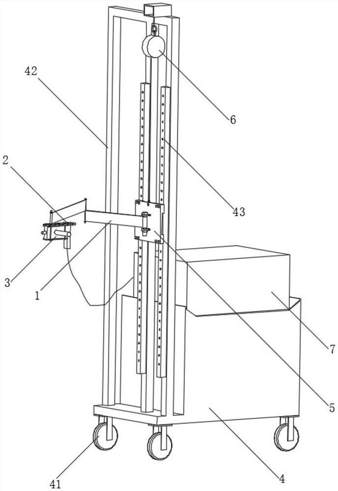
[0022] Such as figure 1 and figure 2 As shown, the tube expansion auxiliary device of the present invention is used to support the expander, so that the expander moves with the guidance of manpower, and realizes tube by row expansion of the shell-and-tube heat exchanger.

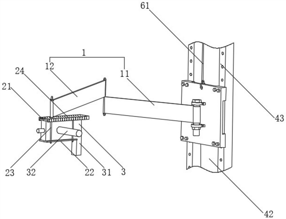
[0023] Such as figure 2 As shown, the expansion tube auxiliary device includes a telescopic joint 1 that moves on the horizontal plane, and the telescopic joint 1 includes a movable plate that is sequentially closed and hinged. The movable plate at the end of the telescopic joint 1 is hinged with a fixed frame 2, which is used to fix the expander. 3. As force is applied to the expander 3, the movable plate rotates relatively, so that the telescopic joint 1 sup...


PUM


Abstract

The invention discloses a pipe expansion auxiliary device. The pipe expansion auxiliary device comprises a telescopic joint moving on the horizontal plane, wherein the telescopic joint comprises movable plates which are sequentially hinged end to end; the movable plate located at the tail end of the telescopic joint is hinged to a fixing frame, and a fixing piece is used for fixing an expander; and therefore, force is applied to the expander, and the movable plates rotate relatively, so that the telescopic joint supports the expander and moves along with the expander. According to the pipe expansion auxiliary device, the expander can be easily moved in the horizontal direction and the vertical direction only on the premise that an operator provides slight directional guiding force, that is, in the process of expanding pipes of a shell-and-tube heat exchanger row by row and one by one, the problems that the labor intensity is high due to the fact that the self weight and the counter-acting force of the expander are completely borne by workers for expansion connection, and the sealing failure is caused due to the fact that the expander and a copper pipe are not concentric due to thefact that the operator holds a pipe expander for expansion connection and shakes are solved.

Description

technical field [0001] The invention belongs to the field of tube expanders, in particular to a tube expansion auxiliary device. Background technique [0002] At present, large-scale commercial air-conditioning shell-and-tube heat exchangers are divided into water side and fluorine side. The water side and fluorine side are required to be sealed without leakage. The water side and fluorine side are generally sealed by copper tube and steel plate to achieve a certain pressure. Sealing effect. In the expansion joint process, the tube expander drives the expander to roll the copper tube at a certain speed and torque, so that the copper tube undergoes plastic deformation and the steel plate undergoes elastic deformation to achieve the sealing effect. [0003] The existing operation method is manual hand-held tube expander moving row by row and root by root. Due to the relatively large torque (generally around 24N.m) during the expansion process, the speed is about 600r / min, and...

Claims


Application Information

Patent Timeline
IPC IPC(8): B21D53/02B21D39/00
CPCB21D53/02B21D39/00
Inventor 王帆李敏甘威彭丹俞孟春陈京京
Owner GREE ELECTRICHEFEI
Why Eureka
Try Eureka