Eureka AIR delivers breakthrough ideas for toughest innovation challenges, trusted by R&D personnel around the world.

Permanent magnet synchronous motor, motor shell and sand core for processing

A motor shell and shell technology, which is applied in the direction of motors, metal processing equipment, cores, etc., can solve the problems of motor size limitation, reduce the height of the machine base, reduce the wall thickness at the highest part of the machine base, etc., and meet the realization limit requirements , the effect of reducing height

Active Publication Date: 2021-02-23
CSR ZHUZHOU ELECTRIC LOCOMOTIVE RES INST
View PDF10 Cites 0 Cited by
  • Summary
  • Abstract
  • Description
  • Claims
  • Application Information

AI Technical Summary

Problems solved by technology

[0003] On some models, due to space constraints, it is necessary to reduce the height of the frame, and when the outer diameter of the stator core is determined, the minimum height can only be achieved by reducing the wall thickness at the highest part of the frame
In this case, the water channel cannot be arranged at the highest part of the machine base, and the spiral water channel cannot be used, resulting in the inability of the water channel to be connected. With the development of new energy industries such as electric vehicle drive systems, electric drive systems are required to be more and more compact. The size of the motor Restrictions, especially in the height direction, are becoming more and more stringent

Method used


Image

  • Permanent magnet synchronous motor, motor shell and sand core for processing
  • Permanent magnet synchronous motor, motor shell and sand core for processing
  • Permanent magnet synchronous motor, motor shell and sand core for processing

Examples


Embodiment Construction

[0025] In view of this, the core of the present invention is to disclose a motor casing to reduce the thickness of the casing while arranging cooling passages. Another core of the present invention is to disclose a sand core used for processing the above-mentioned motor casing and a permanent magnet synchronous motor with the above-mentioned motor casing.

[0026] In order to enable those skilled in the art to better understand the solution of the present invention, the present invention will be further described in detail below in conjunction with the accompanying drawings and specific embodiments.

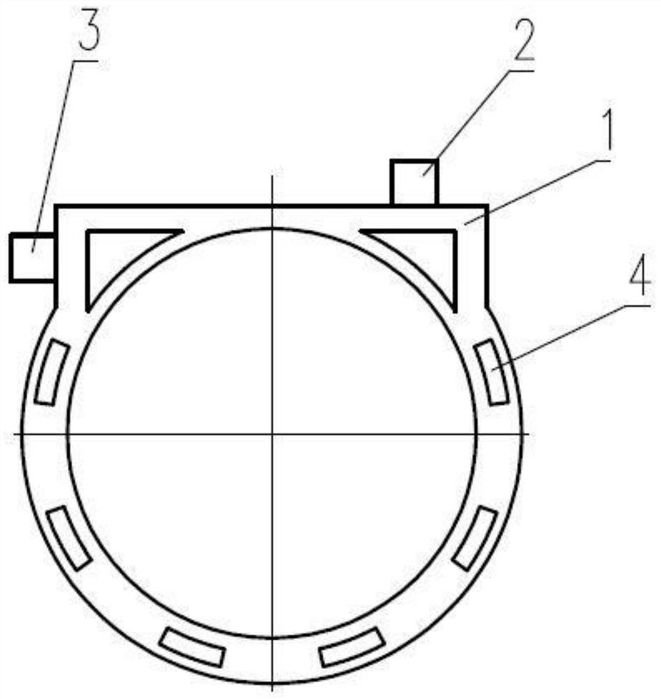
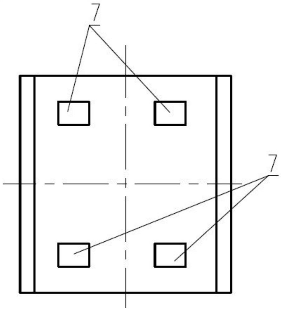
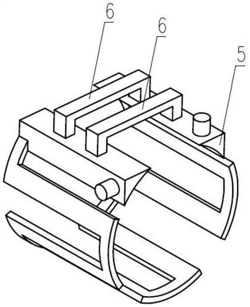
[0027] Such as Figure 1-Figure 4 As shown, the invention discloses a motor casing, which includes a casing body 1 , a water inlet 2 and a water outlet 3 . Wherein, the casing main body 1 has a wave-shaped cooling channel 4 reciprocating in the axial direction, and the casing main body 1 includes a connected first section and a second section along the circumferential direction,...


PUM


Abstract

The invention discloses a permanent magnet synchronous motor and a motor shell thereof. The motor shell comprises a shell main body, a water inlet and a water outlet. The shell main body is provided with a wavy cooling water channel reciprocating along the axial direction, the shell main body comprises a first section and a second section which are connected along the circumferential direction, the first section is located at the top end after the shell main body is installed, the distance between the surface of the first section and the center of the shell main body is smaller than the distance between the surface of the second section and the center of the shell main body, and the cooling water channel is arranged on the second section. The water inlet and the water outlet are both communicated with the cooling water channel and located in the second section. The radial height of the shell main body at the first section is smaller than that of the shell main body at the second section, the cooling water channel is arranged at the second section, and the first section is used as the top end of the shell main body during installation in use, so that the height of the shell main body can be reduced, and the limitation requirement on the motor size is met. The water inlet and the water outlet are formed in the second section, so that the height of the shell main body after installation can be further reduced. In addition, the invention further discloses a sand core for machining the motor shell.

Description

technical field [0001] The invention relates to the technical field of motors, in particular to a permanent magnet synchronous motor, a motor casing and a sand core for processing the motor casing. Background technique [0002] The cooling circuit of the permanent magnet synchronous motor usually adopts an axial reciprocating water channel or a spiral water channel, which generally needs to be covered with water channels in the circumferential direction of the motor. In order to improve the strength of the sand core and the rigidity of the casing, the thickness of the casing is usually more than 20mm. [0003] On some models, due to space constraints, it is necessary to reduce the height of the frame, and when the outer diameter of the stator core is determined, the minimum height can only be achieved by reducing the wall thickness at the highest point of the frame. In this case, the water channel cannot be arranged at the highest part of the machine base, and the spiral wat...

Claims


Application Information

Patent Timeline
Patent Type & Authority Applications(China)
IPC IPC(8): B22C9/22B22C9/06B22C9/10
CPCB22C9/22B22C9/065B22C9/103Y02T10/64
Inventor 陈致初叶文宏胡华石鸿佼胡勇峰史俊旭李伟业
Owner CSR ZHUZHOU ELECTRIC LOCOMOTIVE RES INST
Why Eureka
Eureka Blog
Learn More