Gear extrusion forming equipment for metal powder metallurgy

A technology of pressing equipment and metal powder, which is applied in the field of gear pressing equipment for metal powder metallurgy, and can solve problems such as metal inconvenience

Pending Publication Date: 2021-02-23
韦熙斌
View PDF12 Cites 7 Cited by
  • Summary
  • Abstract
  • Description
  • Claims
  • Application Information

AI Technical Summary

Problems solved by technology

[0004] In order to overcome the shortcomings of the need for manual blanking of the metal powder and the inconvenience of taking out the formed metal in the mold after the metal powder is extruded, the technical problem is to provide an automatic blanking that can be extruded Metal powder metallurgy gear pressing equipment for metal powder ejection

Method used


Image

  • Gear extrusion forming equipment for metal powder metallurgy
  • Gear extrusion forming equipment for metal powder metallurgy
  • Gear extrusion forming equipment for metal powder metallurgy

Examples


Embodiment 1

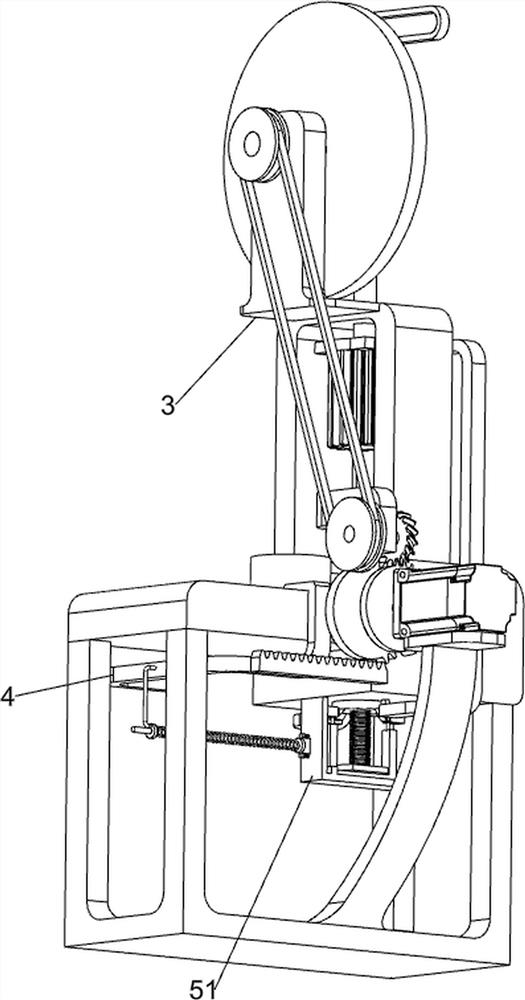
[0028] A gear pressing equipment for metal powder metallurgy, such as figure 1 As shown, it includes a support frame 1, a mold plate 2, a forming mechanism 3, a material spreading mechanism 4 and a material ejection mechanism 5. The upper left side of the support frame 1 is provided with a mold plate 2, and the mold plate 2 is provided with a forming mechanism 3. The plate 2 is provided with a spreading mechanism 4 , and the mold plate 2 is provided with a material ejecting mechanism 5 .

[0029] When the user needs to press the metal powder, this equipment can be used. First, the metal powder that needs to be pressed is placed in the spreading mechanism 4, and the metal powder is moved to the mold plate 2 through the spreading mechanism 4. Mechanism 3 extrudes the metal powder, then lifts the formed metal powder upwards through the ejector mechanism 5 , and pushes the formed metal powder through the spreading mechanism 4 .

Embodiment 2

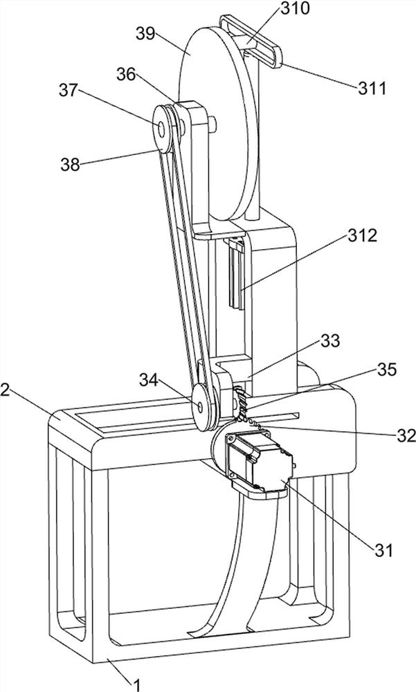
[0031] On the basis of Embodiment 1, as shown in Figure X, the forming mechanism 3 includes a servo motor 31, a missing helical gear 32, a bearing seat 33, a first rotating shaft 34, a full helical gear 35, a mounting frame 36, and a second rotating shaft 37. Pulley assembly 38, turntable 39, eccentric shaft 310, lifting slide rail 311 and pressing mold 312, servo motor 31 is provided on the upper part of support frame 1, and helical gear 32 is provided on the output shaft of servo motor 31, and mold plate 2 The upper right side is provided with a mounting frame 36, the mounting frame 36 is provided with a bearing seat 33, the bearing seat 33 is provided with a first rotating shaft 34, the first rotating shaft 34 is provided with a full helical gear 35, the full helical gear 35 and the missing helical gear 32 meshing, the upper side of the mounting bracket 36 is rotatably provided with a second rotating shaft 37, a pulley assembly 38 is connected between the second rotating sha...

Embodiment 3

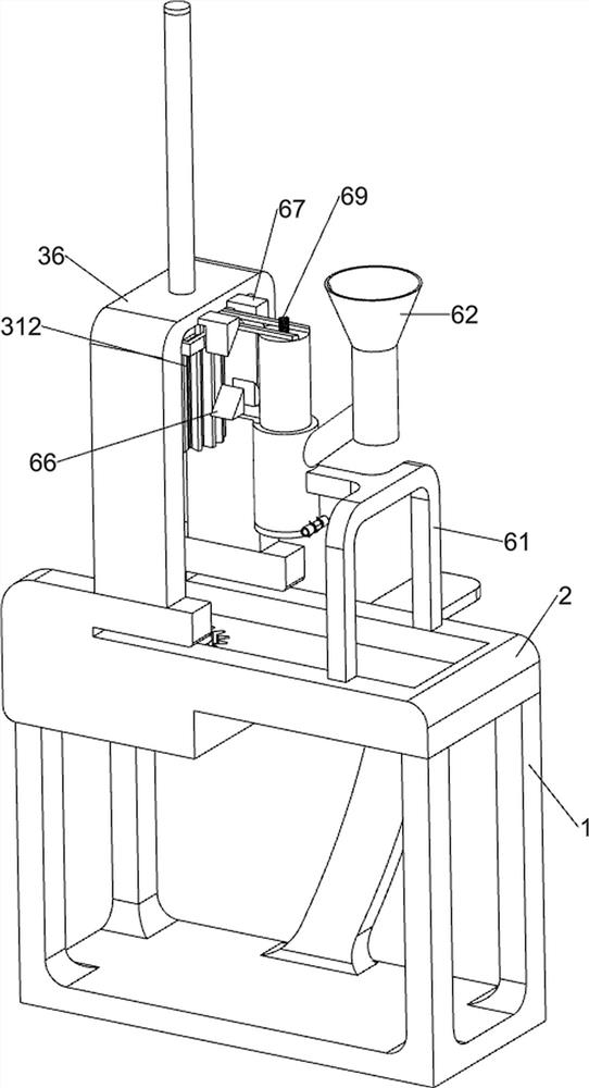
[0038] On the basis of Example 2, such as Figure 8 and Figure 9 As shown, it also includes a blanking mechanism 6, and the blanking mechanism 6 includes a connecting frame 61, a blanking tube 62, a lower pressure column 63, a material retaining plate 64, a torsion spring 65, a first wedge 66, a second wedge 67, sliding bar 68 and the seventh spring 69, mold plate 2 upper left side is provided with connecting frame 61, connecting frame 61 is provided with feeding pipe 62, and the upper feeding pipe 62 slide type is provided with down-pressing column 63, blanking The lower part of the pipe 62 is rotatably provided with a stopper 64, and a torsion spring 65 is connected between the stopper 64 and the feeding pipe 62. The upper side of the feeding pipe 62 is symmetrically provided with a first wedge-shaped block 66, and the lower side of the mounting frame 36 The second wedge-shaped block 67 is arranged symmetrically, and the sliding rod 68 is arranged symmetrically on the pres...


PUM

PropertyMeasurementUnit
sizeaaaaaaaaaa

Abstract

The invention relates to extrusion forming equipment, in particular to gear extrusion forming equipment for metal powder metallurgy. The invention provides the gear extrusion forming equipment for metal powder metallurgy capable of automatically carrying out discharging, and capable of ejecting out metal powder formed through extrusion. The gear extrusion forming equipment for metal powder metallurgy comprises a supporting frame, a die plate, a forming mechanism, a material spreading mechanism and a material ejection mechanism; the supporting frame is used for allowing the whole equipment to be arranged; and the die plate is arranged at the upper portion of the supporting frame; and the forming mechanism is arranged on the die plate, the material spreading mechanism is arranged on the dieplate, and the material ejection mechanism is arranged on the die plate. The gear extrusion forming equipment for metal powder metallurgy achieves the effects that automatic discharging can be achieved, and the metal powder formed through extrusion can be ejected out, the metal powder needing to be subjected to extrusion forming is placed in a discharging pipe, a pressing column moves up and down,the metal powder in the discharging pipe is extruded downwards, and therefore the automatic discharging effect can be achieved.

Description

technical field [0001] The invention relates to a profiling device, in particular to a gear profiling device for metal powder metallurgy. Background technique [0002] Metal powder refers to a group of metal particles with a size less than 1 mm. Including single metal powder, alloy powder and some refractory compound powder with metallic properties, it is the main raw material of powder metallurgy. People recycle the collected metal and make it into powder, then extrude the metal powder, and then smelt the extruded metal powder, so that the metal can be recycled. [0003] In the process of metal extrusion molding, people generally pour the metal to be formed into the mold first, then press the metal in the mold through the pressure plate that fits the mold, and then take out the formed metal, The user keeps repeating the above operations to continuously extrude the metal. In the process of extruding the metal powder, it is necessary to manually unload the metal powder, an...

Claims


Application Information

Patent Timeline
Patent Type & Authority Applications(China)
IPC IPC(8): B22F3/20B22F3/00B22F5/08
CPCB22F3/20B22F3/005B22F5/08
Inventor 韦熙斌
Owner 韦熙斌
Why Eureka
Try Eureka