
Positioning and punching device for circuit breaker production

A punching device and circuit breaker technology, which is applied in the direction of boring/drilling, drilling/drilling equipment, boring machine/drilling machine parts, etc. To improve the efficiency of recycling, improve the accuracy of punching, and improve the effect of environmental protection measures

Inactive Publication Date: 2021-02-23
芜湖君乐电器有限公司
View PDF1 Cites 0 Cited by
  • Summary
  • Abstract
  • Description
  • Claims
  • Application Information

AI Technical Summary

Problems solved by technology

[0004] The purpose of the present invention is to provide a positioning and punching device for circuit breaker production, to solve the problem of the existing circuit breaker production device proposed in the above background technology in the process of use, due to the overall fixation is not firm and there is no relevant punching The device is limited, so that the punched hole will be deflected

Method used


Image

  • Positioning and punching device for circuit breaker production
  • Positioning and punching device for circuit breaker production
  • Positioning and punching device for circuit breaker production

Examples


Embodiment 1

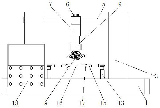
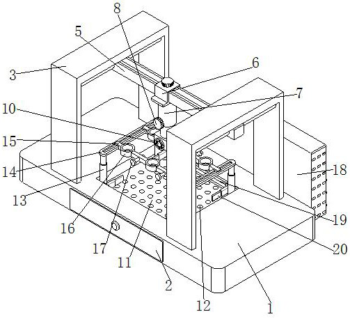
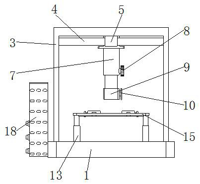
[0025] see Figure 1-5 , the present invention provides a technical solution: a positioning and punching device for circuit breaker production, including a base base 1, a first fixing groove 11 is opened on the top of the base base 1, and both ends of the top of the first fixing groove 11 Both are fixedly installed with the second telescopic rod 13, the top of the second telescopic rod 13 is fixedly equipped with a connecting plate 14, and the external movable connection of the connecting plate 14 is equipped with a second connecting slide bar 15, the second connecting slide bar 15 Positioning holes 16 are opened on the outside, fasteners 17 are installed on one side of the second connecting slide bar 15, and support frames 3 are fixedly installed on both ends of the top of the base base 1, and fixed slide bars are fixedly installed on the bottom of the support frame 3 4. The outer movable part of the fixed sliding rod 4 is equipped with a first connecting sliding rod 5 .

[...

Embodiment 2

[0028] see Figure 1-5 , on the basis of Embodiment 1, the present invention provides a technical solution: the back of the base base 1 is movably installed with a movable drawer 2, the front side of the base base 1 is fixedly installed with a control cabinet 18, and the first fixed groove 11 The inside is provided with a discharge hole 12, and both sides of the first fixed groove 11 are provided with a second fixed groove 19, the inside of the second fixed groove 19 is movably equipped with a slider, and the end of the slider is fixedly installed with a Telescopic limiting plate 20.

[0029] In this embodiment, a movable drawer 2 is movably installed on the back side of the base base 1, so as to facilitate the recycling operation of related waste materials, and a control cabinet 18 is fixedly installed on the front side of the base base 1, so as to facilitate related monitoring of the whole device. Control measures, the inside of the first fixed groove 11 is provided with a ...

Embodiment 3

[0031] Such as Figure 1-5 As shown, on the basis of Embodiment 1 and Embodiment 2, the present invention provides a technical solution: a sliding adjustment block 6 is installed on the outside of the first connecting slide bar 5, and the bottom of the sliding adjustment block 6 is fixedly installed with a first Telescopic rod 7, one side of the first telescopic rod 7 is fixedly installed with the first adjustment knob 8, the bottom of the first telescopic rod 7 is fixedly installed with a limit block 9, and one side of the limit block 9 is fixedly installed with a second Adjust the knob 10, the inside of the limit block 9 is fixedly installed with a first connecting rod 21, the outside of the first connecting rod 21 is fixedly installed with a first connecting ring 22, and both ends of the first connecting ring 22 are fixedly installed with connecting rods. Bolt pieces.

[0032]In this embodiment, the sliding adjustment block 6 is installed through the external movement of t...


PUM


Abstract

The invention discloses a positioning and punching device for circuit breaker production. The positioning and punching device comprises a foundation base, a first fixing groove is formed in the top ofthe foundation base, second extendable rod pieces are fixedly installed at the two ends of the top of the first fixing groove, and connecting plate pieces are fixedly installed at the tops of the second extendable rod pieces; and second connecting sliding rods are movably installed outside the connecting plate pieces, positioning holes are formed in the outer portions of the second connecting sliding rods, fasteners are movably installed on one sides of the second connecting sliding rods, supporting frames are fixedly installed at the two ends of the top of the foundation base, and fixed sliding rods are fixedly installed at the bottoms of the supporting frames. The positioning and punching device has the beneficial effects that by arranging related devices such as the second extendable rod pieces and the second connecting sliding rods, related fixing operation can be carried out on a related circuit breaker, so that the slipping phenomenon of the circuit breaker in the punching process is avoided, the deviation phenomenon of the circuit breaker in the punching process can be effectively avoided, and meanwhile, the overall punching precision is also improved.

Description

technical field [0001] The invention belongs to the technical field of mechanical processing, and in particular relates to a positioning and punching device for circuit breaker production. Background technique [0002] A circuit breaker refers to a switching device that can close, carry and break current under normal circuit conditions, and can close, carry and break current under abnormal circuit conditions within a specified time. It can be used to distribute electrical energy. Frequent starting of asynchronous motors, protection of power lines and motors, etc., has a wide range of applications. Among them, when the above-mentioned equipment is overloaded or short-circuited, it can automatically cut off the circuit, and generally does not need to change parts after breaking the fault current. . [0003] Usual positioning and punching device such as the publication number is a kind of punching and positioning device of CN103706842A, by arranging related drill bits, workpie...

Claims


Application Information

Patent Timeline
Patent Type & Authority Applications(China)
IPC IPC(8): B23B41/00B23B47/00B23Q11/00B23Q11/08
CPCB23B41/00B23B47/00B23Q11/0046B23Q11/08
Inventor 王耀
Owner 芜湖君乐电器有限公司
Learn More