
Punching device for building construction

A drilling device and technology for building construction, applied in the direction of work accessories, manufacturing tools, stone processing tools, etc., can solve problems affecting installation, deviation, poor drilling accuracy, etc.

Inactive Publication Date: 2021-02-23
朱皓
View PDF0 Cites 1 Cited by
  • Summary
  • Abstract
  • Description
  • Claims
  • Application Information

AI Technical Summary

Problems solved by technology

[0002] In the process of building construction, in order to assist in the installation, it is often necessary to drill holes on the wall. Most of the installation holes are perpendicular to the wall, but there are also some installation holes that are inclined. When drilling, the operator needs to The punching machine is tilted at a certain angle relative to the wall to punch holes. This method of punching oblique holes requires manual control of the angle of inclination, and the drilling accuracy is poor. It is easy to cause deviations in the angle of the oblique holes, which will affect the subsequent installation; During the process, the operator needs to hold the punching machine with his arm, which will easily cause muscle soreness in his arm after a long time

Method used


Image

  • Punching device for building construction
  • Punching device for building construction
  • Punching device for building construction

Examples


Embodiment 1

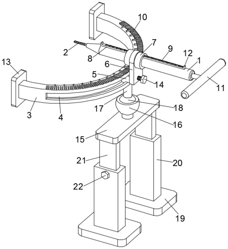
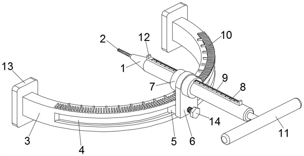
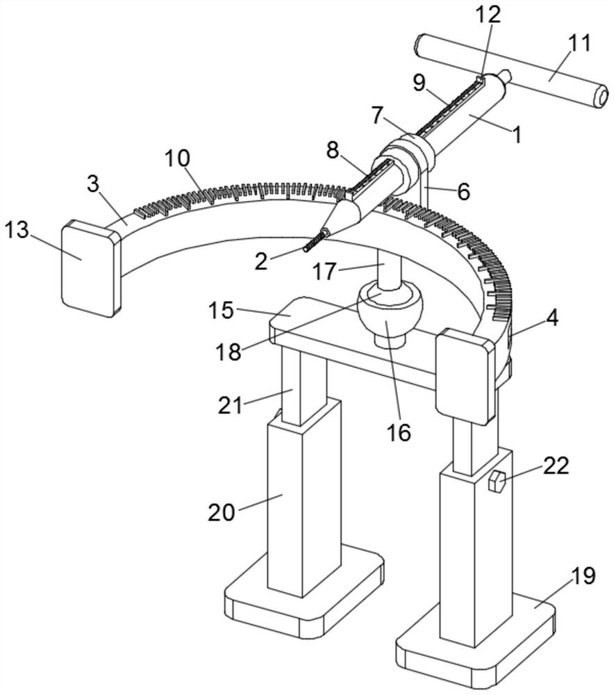
[0023] see Figure 1-2 , a drilling device for building construction, including a fuselage 1 and a support plate 15, a drill bit 2 is installed on the fuselage 1, and a ring frame 3, and a chute 4 is provided on the ring frame 3, and the A slider 5 is slidably embedded in the chute 4, a mounting plate 6 is fixed on the slider 5, a sleeve 7 is fixedly sleeved on the upper end of the mounting plate 6, and the fuselage 1 is slidably sleeved on the sleeve 7. Inside, the fuselage 7 is fixed with a sliding bar 8 that moves through the sleeve 7, the sliding bar 8 is provided with a hole depth line 9 for indicating the depth of the punching, and the ring frame 3 is provided with a Angle line 10 for punching angle;

[0024] see image 3 A ball sleeve 16 is fixedly installed on the upper end surface of the support plate 15, a fixed column 17 is installed on the bottom surface of the ring frame 3, and an adjustment ball 18 is installed at the lower end of the fixed column 17, and the a...

Embodiment 2

[0034] A drilling device for building construction, comprising a fuselage 1 and a support plate 15, a drill bit 2 is installed on the fuselage 1, and a ring frame 3, a chute 4 is provided on the ring frame 3, and the slide A slider 5 is slidably embedded in the slot 4, a mounting plate 6 is fixed on the slider 5, a sleeve 7 is fixedly sleeved on the upper end of the mounting plate 6, and the fuselage 1 is slidably sleeved in the sleeve 7 , the fuselage 7 is fixed with a slide bar 8 that moves through the sleeve 7, the slide bar 8 is provided with a hole depth line 9 for indicating the depth of the punching hole, and the ring frame 3 is provided with a hole depth line 9 for indicating the punching depth. The angle line 10 of the hole angle; the upper end surface of the support plate 15 is fixedly equipped with a ball sleeve 16, the bottom surface of the ring frame 3 is equipped with a fixed column 17, and the lower end of the fixed column 17 is equipped with an adjustment ball 1...


PUM


Abstract

The invention discloses a punching device for building construction. The punching device comprises a machine body, a supporting plate and an annular frame, wherein a drill bit is installed on the machine body; a sliding groove is formed in the annular frame; a sliding block is embedded in the sliding groove in a sliding manner; a sleeve is fixed on the sliding block through an installation plate;the machine body is slidably sleeved with the sleeve; a sliding strip is arranged on the machine body; hole depth lines are arranged on the sliding strip; and angle lines are arranged on the annular frame. The punching device for the building construction is provided with the annular frame, the sleeve is slidably installed on the annular frame, the machine body is slidably sleeved with the sleeve,and an adjusting ball is installed at the bottom of the annular frame, so that the machine body is adjusted at different inclination angles, and inclined holes with different angles are machined; theangle lines are arranged on the annular frame, and the angles of the inclined holes can be accurately adjusted through the angle lines; the hole depth lines are arranged on the machine body, so thatthe hole depths are observed in real time and made to meet the installation requirement; and the punching device is stable and reliable to use and high in safety, does not cause painful arm muscles ofoperators, and simultaneously ensures the drilling quality.

Description

technical field [0001] The invention relates to the technical field of building construction, in particular to a drilling device for building construction. Background technique [0002] In the process of building construction, in order to assist in the installation, it is often necessary to drill holes on the wall. Most of the installation holes are perpendicular to the wall, but there are also some installation holes that are inclined. When drilling, the operator needs to The punching machine is tilted at a certain angle relative to the wall to punch holes. This method of punching oblique holes requires manual control of the angle of inclination, and the drilling accuracy is poor. It is easy to cause deviations in the angle of the oblique holes, which will affect subsequent installation; During the process, the operator needs to hold the punching machine with his arm, which will easily cause muscle soreness in his arm after a long time. Contents of the invention [0003]...

Claims


Application Information

Patent Timeline
Patent Type & Authority Applications(China)
IPC IPC(8): B28D1/14B28D7/00
CPCB28D1/14B28D7/00
Inventor 朱皓
Owner 朱皓
Learn More