Sewage upper-layer floating foam suction device

A suction device and foam technology, applied in the direction of grease/oily substance/floating matter removal device, liquid separation, separation method, etc., can solve the problem of difficult cleaning of floating matter, achieve the effect of convenient operation, low cost, and improved efficiency

Inactive Publication Date: 2021-02-23
XINCHANG DELAO SEWAGE TREATMENT CO LTD
View PDF0 Cites 0 Cited by
  • Summary
  • Abstract
  • Description
  • Claims
  • Application Information

AI Technical Summary

Problems solved by technology

[0003] The technical problem to be solved by the present invention is to provide a suction device for floating foam in the upper layer of sewage, which overcomes the problem of difficult cleaning of floating objects in the upper layer of sewage, and realizes automatic suction and cleaning of floating objects in the upper layer of sewage

Method used


Image

  • Sewage upper-layer floating foam suction device
  • Sewage upper-layer floating foam suction device
  • Sewage upper-layer floating foam suction device

Examples


Embodiment Construction

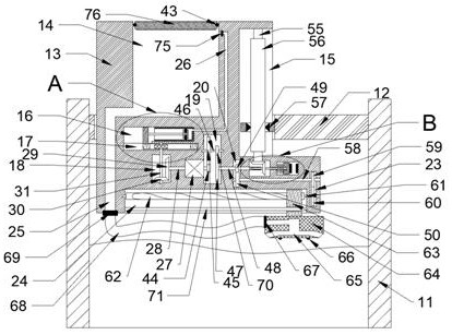
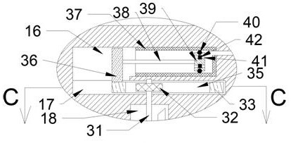
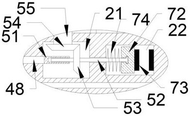
[0016] Combine below Figure 1-4 The present invention is described in detail, wherein, for the convenience of description, the orientations mentioned below are defined as follows: figure 1 The up, down, left, right, front and back directions of the projection relationship itself are the same.

[0017] combined with Figure 1-4 Described a kind of sewage upper layer floating foam absorbing device comprises frame 11 and panel 12 fixedly connected on the frame 11 and the elevator 13 that is slidably connected in the panel 12, and described elevator 13 is provided with opening upwards. The collection chamber 14, the lead screw chamber 15 located on the right side of the collection chamber 14 and opening to the right, the piston chamber 16 located on the lower side of the collection chamber 14, the piston chamber 16 located in the lower wall of the piston chamber 16 and connected to the piston The reciprocating chamber 17 communicated with the chamber 16, the translation chamber...


PUM


Abstract

The invention discloses a sewage upper-layer floating foam suction device which comprises a frame, a panel fixedly connected to the frame and a lifter slidably connected into the panel. A collecting cavity with an upward opening, a lead screw cavity located on the right side of the collecting cavity and provided with a rightward opening, a piston cavity located on the lower side of the collectingcavity, a reciprocating cavity located in the lower cavity wall of the piston cavity and communicated with the piston cavity, and a translation cavity located on the lower side of the reciprocating cavity and provided with a downward opening are formed in the lifter. The reversing transmission cavity is located between the translation cavity and the reciprocating cavity, the speed reducer cavity is located on the right side of the reversing transmission cavity, the middle transmission cavity is located on the right side of the speed reducer cavity, and the lead screw input cavity is located onthe right side of the middle transmission cavity. Therefore, the device can be automatically adjusted to the height of the floaters only by placing the device in the sewage that needs to be treated,and the floaters are sucked into a special containing cavity in the device in a sucking mode to be treated in a centralized mode.

Description

technical field [0001] The industrial sewage treatment equipment of the present invention is specifically a floating foam absorption device for the upper layer of sewage. Background technique [0002] There are many kinds of pollutants in the sewage discharged by industry, some of which are foam-filled substances floating on the upper layer of the sewage. Generally, the cleaning of this kind of substance is very troublesome, because it is always in the upper layer of the liquid and cannot be disposed of by dumping. At the same time, they It also has a certain degree of fluidity, and in many cases, it is necessary to solve this part of the floating matter in the treatment of sewage, which makes the treatment of sewage a lot more difficult. Contents of the invention [0003] The technical problem to be solved by the present invention is to provide a suction device for floating foam in the upper layer of sewage, which overcomes the problem that the floating objects in the upp...

Claims


Application Information

Patent Timeline
Patent Type & Authority Applications(China)
IPC IPC(8): C02F1/40
CPCC02F1/40
Inventor 黄家家
Owner XINCHANG DELAO SEWAGE TREATMENT CO LTD
Why Eureka
Try Eureka