Method for cleaning bottom of manual plate steel door
A steel and manual technology, applied in the direction of cleaning methods using tools, cleaning methods and utensils, chemical instruments and methods, etc., can solve the problems of easy accumulation of dirt and inconvenient cleaning, so as to facilitate cleaning, reduce cleaning difficulty and improve convenience sexual effect
- Summary
- Abstract
- Description
- Claims
- Application Information
AI Technical Summary
Problems solved by technology
Method used
Image
Examples
Embodiment 1
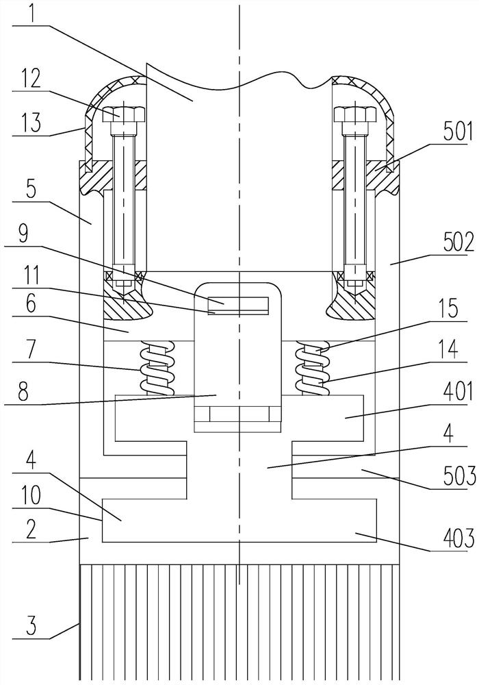
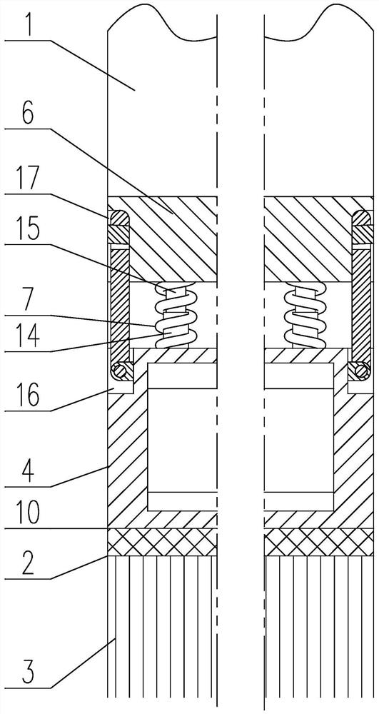
[0045] A method for cleaning the bottom of a manual plate steel door, such as figure 1 with figure 2 As shown, it includes the following steps:
[0046] S1. Fix the bearing strip 6 on the bottom of the door panel 1, and the axis of the bearing strip 6 is parallel to the width direction of the door panel 1;
[0047]S2. Insert the lower horizontal plate B401 of the middle bar 4 with an I-shaped cross section into the chute 10 on the carrier 2, and the axis of the chute 10 is parallel to the axis of the carrier bar 6, and the carrier 2 is an elastic rubber strip. Its axis is parallel to the axis of the carrying bar 6, and its bottom is connected with the bristles 3;
[0048] S4, the top of the upper horizontal plate B401 of the middle bar 4 is connected with the bottom of the carrier bar 6 by the spring 7, and the axis of the middle bar 4 is parallel to the axis of the carrier bar 6, and the telescopic direction of the spring 7 is perpendicular to the ground;
[0049] S5. Ins...
Embodiment 2
[0056] This embodiment is based on Embodiment 1 to further optimize the description of the present invention.
[0057] Such as figure 1 with figure 2 As mentioned above, in the present invention, two U-shaped bar steels 5 are symmetrically arranged on both sides of the middle bar 4 and along the center line parallel to the width direction on the bottom surface of the door panel 1, and the upper level of the U-shaped bar steel 5 The plate A501 is connected with the extension of the load bar 6, its vertical plate A502 extends downward, its lower horizontal plate A503 is located between the upper horizontal plate B401 and the lower horizontal plate B403, and the end of the lower horizontal plate A503 is connected to the side of the vertical plate B402 wall fit;
[0058] And the top surface of the bearing part 2 is attached to the lower surface of the lower horizontal plate A503 , the top surface of the bearing part 2 is in a compressed state, and the lower horizontal plate B40...
Embodiment 3
[0066] This embodiment is to further illustrate the structure of the spring 7 .
[0067] Such as figure 1 As shown, the inner side of the spring 7 is provided with a sleeve 14 and an insertion rod 15 whose axes coincide with each other. It is connected, and its bottom end is inserted in the sleeve 14, and there is a distance from the bottom of the inner hole of the sleeve 14.
[0068] The sleeve 14 and the plunger 15 guide the compression of the spring 7 to prevent its non-axial deformation and ensure the stability of the entire mechanism structure and performance.
PUM
 Abstract
Description
Claims
Application Information
 - R&D
- Intellectual Property
- Life Sciences
- Materials
- Tech Scout
- Unparalleled Data Quality
- Higher Quality Content
- 60% Fewer Hallucinations
Browse by: Latest US Patents, China's latest patents, Technical Efficacy Thesaurus, Application Domain, Technology Topic, Popular Technical Reports.
© 2025 PatSnap. All rights reserved.Legal|Privacy policy|Modern Slavery Act Transparency Statement|Sitemap|About US| Contact US: help@patsnap.com


