Pipe-jacking hole-entering sealing ring beam structure

A sealing ring and beam structure technology, applied in the direction of pipes, pipes/pipe joints/pipe fittings, mechanical equipment, etc., can solve the damage to the surrounding environment and economic waste, water leakage from pipes and receiving well walls, and groundwater levels The following problems can achieve the effect of mitigating groundwater leakage, improving service life and reducing differential settlement

Pending Publication Date: 2021-02-23
SHANGHAI URBAN CONSTR DESIGN RES INST GRP CO LTD
View PDF7 Cites 2 Cited by
  • Summary
  • Abstract
  • Description
  • Claims
  • Application Information

AI Technical Summary

Problems solved by technology

However, after the pipe jacking enters the receiving hole of the receiving well, the gap of about 100 mm between the pipe joint and the well wall casing is generally only sealed with flexible materials such as cement; at the same time, all pipe jacking pipes are basically located below the ground depth, and often below the groundwater level; at the same time, there is a change in the water level in the pipeline, and it is subjected to working conditions such as the self-weight of the upper water and soil, and the ground load. diff

Method used


Image

  • Pipe-jacking hole-entering sealing ring beam structure
  • Pipe-jacking hole-entering sealing ring beam structure

Examples


Embodiment

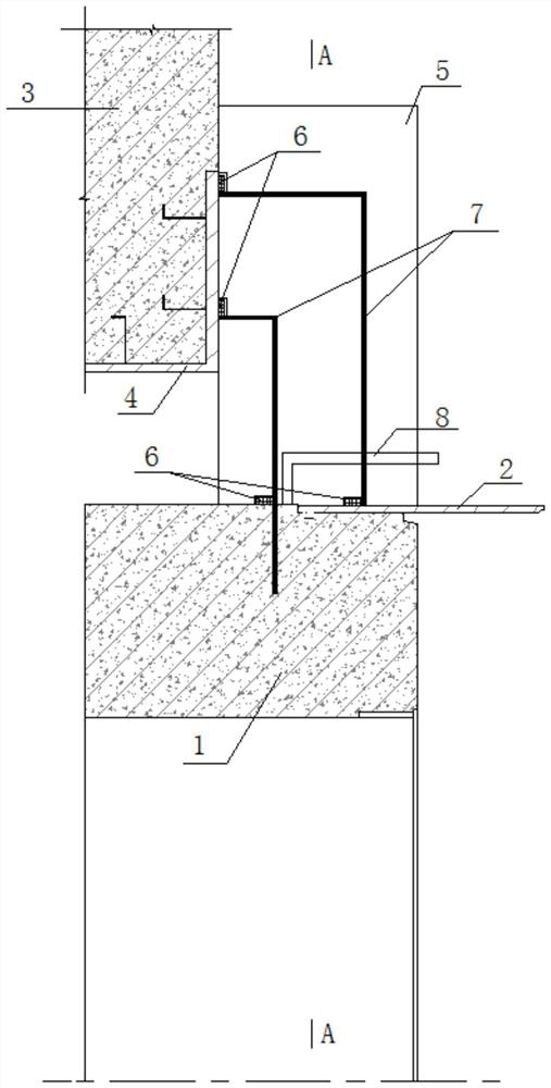
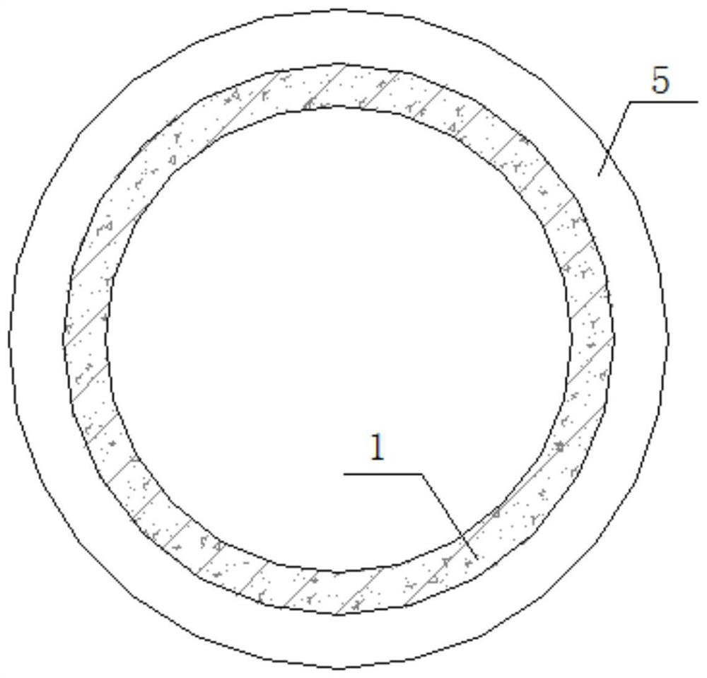
[0017] Such as Figure 1-Figure 2 As shown, a pipe jacking hole sealing ring beam structure includes a pipe jacking joint 1, a pipe joint socket 2, a receiving well wall 3, a well wall pre-buried casing 4 and a sealing ring beam 5;

[0018] The end of the pipe jacking joint 1 is provided with a pipe joint socket 2, the pipe jacking joint 1 is located in the embedded casing 4 of the well wall, the embedded casing 4 of the well wall is arranged in the well wall 3 of the receiving well, and the embedded casing There is a gap between 4 and the pipe jacking joint 1, the pipe jacking joint 1 is fixed in the pre-embedded casing 4 of the well wall through the joint socket 2, and the sealing ring beam 5 is connected with the pipe joint socket 2 and the well wall pre-buried The casing pipes 4 are respectively fixed by anchoring steel bars 7, and water-stop strips 6 are respectively arranged between the sealing ring beam 5, the well wall 3 of the receiving well, and the pipe jacking join...


PUM


Abstract

The invention discloses a pipe-jacking hole-entering sealing ring beam structure. The pipe-jacking hole-entering sealing ring beam structure comprises a pipe-jacking pipe joint, a pipe joint socket, areceiving well wall, a well wall pre-buried casing pipe and a sealing ring beam; the pipe joint socket is arranged at the end of the pipe-jacking pipe joint; the pipe-jacking pipe joint is located inthe well wall pre-buried casing pipe; the well wall pre-buried casing pipe is arranged in the receiving well wall; a gap is reserved between the pre-buried casing pipe and the pipe-jacking pipe joint; and the pipe-jacking pipe joint is fixed in the well wall pre-buried casing pipe through the pipe joint socket. According to the pipe-jacking hole-entering sealing ring beam structure, the pre-buried casing pipe and the pipe joint socket of the receiving well wall are fully utilized and are connected with a steel structure through anchoring steel bars; then the cast-in-place reinforced concretesealing ring beam is implemented, so that differential settlement between the pipe-jacking pipe joint and the receiving well wall can be greatly reduced; and underground water leakage, ground subsidence and the like in a gap between the pipe-jacking pipe joint and the well wall pre-buried casing pipe are relieved, and the service life of the structure is prolonged.

Description

technical field [0001] The invention relates to the technical field of pipe jacking hole sealing, in particular to a ring beam structure for pipe jacking hole sealing. Background technique [0002] At present, the pipe jacking construction method plays an important role in the field of urban municipal public pipelines, and has a wide range of applications. However, after the pipe jacking enters the receiving hole of the receiving well, the gap of about 100 mm between the pipe joint and the well wall casing is generally only sealed with flexible materials such as cement; at the same time, all pipe jacking pipes are basically located below the ground depth, and often below the groundwater level; at the same time, there is a change in the water level in the pipeline, and it is subjected to working conditions such as the self-weight of the upper water and soil, and the ground load. differential settlement. Therefore, water leakage often occurs in the gap between the pipeline a...

Claims


Application Information

Patent Timeline
IPC IPC(8): F16L5/00F16L5/02
CPCF16L5/00F16L5/02
Inventor 吴绍珍张波
Owner SHANGHAI URBAN CONSTR DESIGN RES INST GRP CO LTD
Why Eureka
Try Eureka