
On-site detection positioning tool in engineering detection test

A technology for on-site inspection and engineering inspection, applied in the direction of testing the hardness of materials, measuring devices, instruments, etc., can solve the problems of inconvenient carrying and large volume

Pending Publication Date: 2021-02-23
江苏房城建设工程质量检测有限公司
View PDF0 Cites 0 Cited by
  • Summary
  • Abstract
  • Description
  • Claims
  • Application Information

AI Technical Summary

Problems solved by technology

[0002] With the progress of society, our safety awareness is getting higher and higher, the detection methods are becoming more and more abundant, and the ability to deal with potential dangers is getting stronger and stronger, especially in this aspect of the building. There are various detection methods, for example, Standard DBJ01-78-2003 and JCJ / 23-2001 technical specification for testing concrete compressive strength by rebound method We can know how to test the quality of concrete, which stipulates that the area of ​​the measurement area should not be greater than 0.04 square meters, and the measurement points should be distributed The net distance between two evenly adjacent points should not be less than 20 mm, 16 rebound values ​​in one measurement area, two symmetrical measurable surfaces of the easy-to-select components in the measurement area, or on one measurable surface, the distribution must be uniform, and the concrete surface is clean and smooth In order to ensure that the 16 measuring points in a survey area are evenly distributed, detection and positioning tools are generally used to mark partitions, but the existing detection and positioning tools have a simple structure, usually a grid, and the grid is large in size and inconvenient to carry

Method used


Image

  • On-site detection positioning tool in engineering detection test
  • On-site detection positioning tool in engineering detection test
  • On-site detection positioning tool in engineering detection test

Examples


Embodiment Construction

[0018] The following will clearly and completely describe the technical solutions in the embodiments of the present invention with reference to the accompanying drawings in the embodiments of the present invention. Obviously, the described embodiments are only some, not all, embodiments of the present invention. Based on the embodiments of the present invention, all other embodiments obtained by persons of ordinary skill in the art without making creative efforts belong to the protection scope of the present invention.

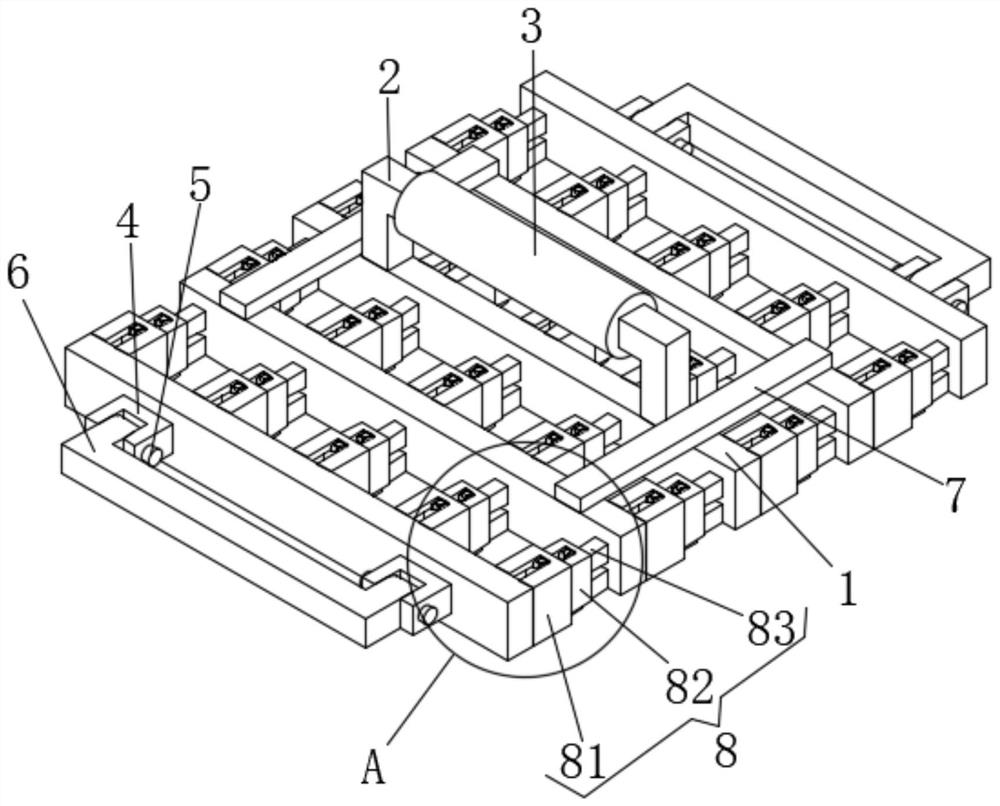
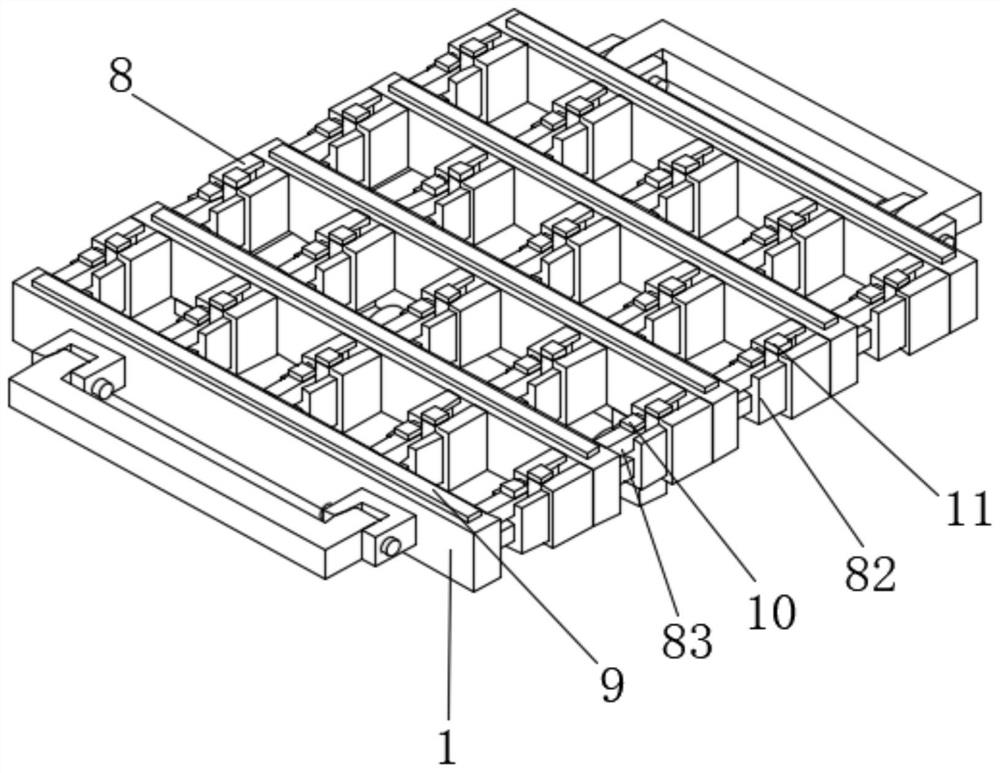
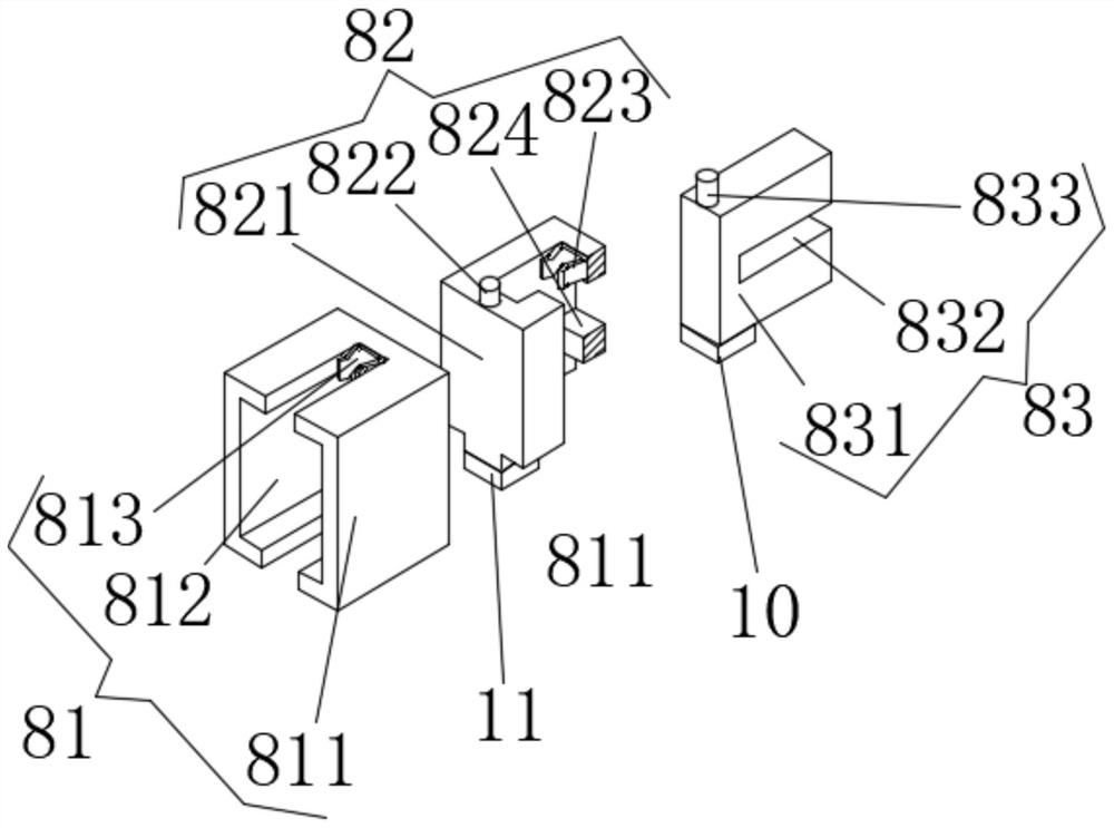
[0019] see Figure 1-4 , the present invention provides a technical solution: an on-site detection and positioning tool in an engineering detection test, including a vertical support 1 and a telescopic mechanism 8;

[0020] Vertical support 1: its lower surface is provided with sponge strips 9, and the upper surface of the vertical support 1 in the middle is provided with a handle 2, and the middle part of the outer surface of the handle 2 is provided with a r...


PUM


Abstract

The invention discloses an on-site detection positioning tool in an engineering detection test. The on-site detection positioning tool comprises longitudinal supports and telescopic mechanisms; spongestrips are arranged on the lower surfaces of the longitudinal supports, a handle is arranged on the upper surface of the longitudinal support in the middle, a rubber sleeve is arranged in the middleof the outer surface of the handle, rotating shaft seats are symmetrically distributed on the opposite faces of the longitudinal supports on the two sides, the rotating shaft seats on the same side are rotationally connected with the two ends of the handle through rotating shafts correspondingly, and the lower surfaces of the transverse supports are in sliding connection with the upper surfaces ofthe corresponding transverse supports; and one telescopic mechanism is arranged between every two adjacent longitudinal supports, and the lower surfaces of the telescopic mechanisms are provided withfirst sponge blocks and second sponge blocks. A field detection positioning tool in the engineering detection test can stretch out and draw back in a two-stage mode, is convenient to fold and operate, convenient to carry, capable of achieving positioning when stretching out, capable of preventing free folding and capable of guaranteeing use stability.

Description

technical field [0001] The invention relates to the technical field of positioning tools, in particular to an on-site detection and positioning tool in engineering detection tests. Background technique [0002] With the progress of society, our safety awareness is getting higher and higher, the detection methods are becoming more and more abundant, and the ability to deal with potential dangers is getting stronger and stronger, especially in this aspect of the building. There are various detection methods, for example, Standard DBJ01-78-2003 and JCJ / 23-2001 technical specification for testing concrete compressive strength by rebound method We can know how to test the quality of concrete, which stipulates that the area of ​​the measurement area should not be greater than 0.04 square meters, and the measurement points should be distributed The net distance between two evenly adjacent points should not be less than 20 mm, 16 rebound values ​​in one measurement area, two symmetr...

Claims


Application Information

Patent Timeline
Patent Type & Authority Applications(China)
IPC IPC(8): G01N3/02G01N3/04G01N3/52
CPCG01N3/02G01N3/04G01N3/52
Inventor 陈根清杨建秋
Owner 江苏房城建设工程质量检测有限公司
Learn More