Deep cryogenic temperature control system for power devices
A technology for temperature control systems and power devices, applied in semiconductor devices, electric solid state devices, semiconductor/solid state device components, etc., and can solve problems such as lack of deep and low temperature background cooling systems
- Summary
- Abstract
- Description
- Claims
- Application Information
AI Technical Summary
Problems solved by technology
Method used
Image

Examples
Embodiment 1
[0067]In order to overcome the above-mentioned defects currently existing, this embodiment provides a cryogenic temperature control system for power devices. The cryogenic temperature control system includes: a liquid storage tank for storing various At least one of the cooling liquids; a gas supply module connected to the liquid storage tank and used to provide compressed gases of different pressures into the liquid storage tank to squeeze out the cooling liquid in the liquid storage tank; a fluid pipeline, connected to the liquid storage tank, and used to flow the cooling liquid squeezed out of the liquid storage tank to a target heat load according to different flow rates, so as to cool the target heat load , the flow rate of the cooling liquid in the fluid pipeline is associated with the pressure of the compressed gas provided by the gas supply module; and, a control module is connected in communication with the gas supply module and the target heat load, respectively , an...
Embodiment 2
[0076] On the basis of Embodiment 1, this embodiment provides a cryogenic temperature control system for power devices, and the cryogenic temperature control system includes a testing device.
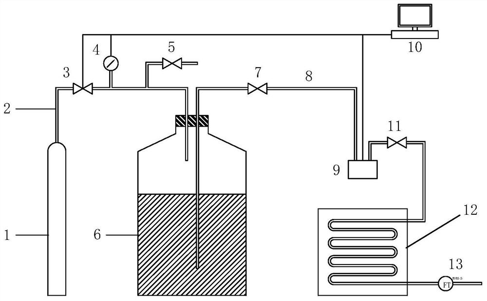
[0077] Such as figure 1 As shown, the test device mainly includes a gas supply module, a liquid storage tank 6 , a fluid pipeline 8 , a filling valve 7 , a control module 10 , a liquid outlet valve 11 , a heat exchanger 12 and a gas mass flow meter 13 .
[0078] Specifically, the gas supply module mainly includes a gas source 1 , a gas pipeline 2 , an electronically controlled pressure regulating valve 3 , a barometer 4 and an air release valve 5 .
[0079] Such as figure 1 As shown, the gas pipeline 2 is respectively connected with the gas source 1, the electronically controlled pressure regulating valve 3, the air pressure gauge 4 and the air release valve 5 through hydraulic joints (not shown in the figure) to ensure the airtightness of the gas pipeline.
[0080] Specifically, the ...
Embodiment 3
[0106] On the basis of Embodiment 1 and Embodiment 2, this embodiment provides a cryogenic temperature control system for power devices, the cryogenic temperature control system includes an operating device.
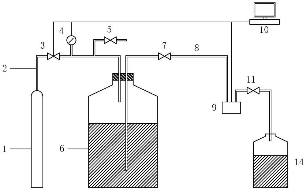
[0107] Such as figure 2 As shown, the main difference between the operating device of this embodiment and the test device of embodiment 2 is: the operating device also includes a liquid collection tank 14, but does not include the heat exchanger 12 and the gas mass flow rate of the test device of embodiment 2 Count 13. In this embodiment, other components of the operating device are basically the same or similar to the testing device in Embodiment 2, so details are not described again.
[0108]In this embodiment, the liquid outlet valve 11 is connected to the low-temperature fluid pipeline 8 through a hydraulic joint, and the low-temperature fluid pipeline 8 directly extends into the liquid collection tank 14 .
[0109] The liquid collection tank 14 is used to collect...
PUM
 Abstract
Description
Claims
Application Information
 - R&D
- Intellectual Property
- Life Sciences
- Materials
- Tech Scout
- Unparalleled Data Quality
- Higher Quality Content
- 60% Fewer Hallucinations
Browse by: Latest US Patents, China's latest patents, Technical Efficacy Thesaurus, Application Domain, Technology Topic, Popular Technical Reports.
© 2025 PatSnap. All rights reserved.Legal|Privacy policy|Modern Slavery Act Transparency Statement|Sitemap|About US| Contact US: help@patsnap.com