Moisture-proof power distribution cabinet
A power distribution cabinet and cabinet technology, which is applied in the substation/distribution device shell, electrical components, substation/switch layout details, etc. and other problems to achieve the effect of reducing loss, preventing corrosion and aging, and keeping dry
- Summary
- Abstract
- Description
- Claims
- Application Information
AI Technical Summary
Problems solved by technology
Method used
Image
Examples
Embodiment 1
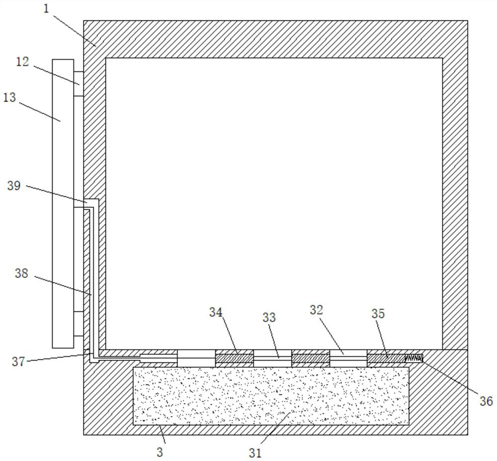
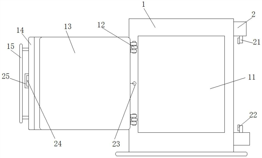
[0032] see figure 1 , a moisture-proof power distribution cabinet, comprising a cabinet body 1, the cabinet body 1 is provided with a cabinet door 13 that can be opened and closed, and a door handle 15 is fixedly connected on one side of the cabinet door 13;
[0033] A storage tank 3 is arranged in the inner wall of the cabinet body 1 , and a desiccant 31 is stored in the storage tank 3 . 32.
[0034] The design of the storage tank 3 and the desiccant 31 can effectively absorb the moisture in the cabinet 1 by using the desiccant, thereby realizing the moisture resistance in the cabinet 1 .
[0035] Further, the cabinet body 1 located on the side of the drying hole 32 is provided with a collection groove 34 , and the collection groove 34 is provided with a sliding connection sealing plate 35 , and a phase between the adjacent sealing plates 35 is provided. The connecting rod 33 is connected, and the collecting groove 34 at one end of the storage groove 3 is provided with a pl...
Embodiment 2
[0039] The same point with Example 1 is not repeated, and the difference with Example 1 is:
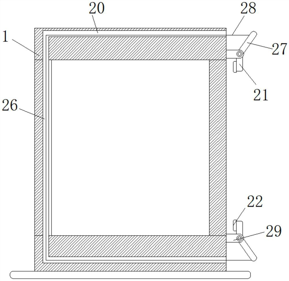
[0040] see Figure 2-6 , the cabinet door 13 on one side of the door handle 15 is provided with a fixed plate 14 for fixed connection;
[0041] One side of the cabinet body 1 is provided with a self-locking mechanism for closing the cabinet door 13 . The self-locking mechanism includes a lock plate 21 , a lock rope 28 , an unlocking ring 25 and a transmission rope 24 , and the unlocking ring 25 is located on the door handle 15 . Inside, one side of the cabinet body 1 is provided with positioning blocks 29 that are symmetrically distributed up and down and fixedly connected. The extending end of the positioning block 29 is provided with a second adjusting groove 292, and the second adjusting groove 292 is provided with a movable connection. The connecting shaft 291, one end of the connecting shaft 291 is provided with a locking plate 21 that is fixedly connected and used for pressing an...
Embodiment 3
[0050] The same point with embodiment 2 is not repeated, and the difference with embodiment 2 is:
[0051] see Figure 7-10 , the cabinet 1 includes a base 4, the base 4 is square, a first cabinet plate 45 fixedly connected on one side of the base 4, and a cover plate 42 matching the base 4 is arranged above the base 4, the said One side of the cover plate 42 and the upper end of the first cabinet plate 45 are rotatably connected by a first hinge 43, and the two sides of the first cabinet plate 45 between the cover plate 42 and the base 4 are provided with a second cabinet that is rotatably connected. The upper end of the second cabinet plate 41 is provided with a plurality of first positioning holes 413 , and both ends of the bottom of the cover plate 42 are provided with a plurality of first positioning holes 413 that are fixedly connected and engaged with the first positioning holes 413 . For the positioning rods 421 , the outer side of one of the second cabinet panels 41 ...
PUM
 Abstract
Description
Claims
Application Information
 - R&D
- Intellectual Property
- Life Sciences
- Materials
- Tech Scout
- Unparalleled Data Quality
- Higher Quality Content
- 60% Fewer Hallucinations
Browse by: Latest US Patents, China's latest patents, Technical Efficacy Thesaurus, Application Domain, Technology Topic, Popular Technical Reports.
© 2025 PatSnap. All rights reserved.Legal|Privacy policy|Modern Slavery Act Transparency Statement|Sitemap|About US| Contact US: help@patsnap.com


