A high-speed optical signal generating device and control method thereof
A technology for generating devices and optical signals, applied in the field of optical communication, to achieve the effect of continuous central wavelength
- Summary
- Abstract
- Description
- Claims
- Application Information
AI Technical Summary
Problems solved by technology
Method used
Image
Examples
Embodiment 1
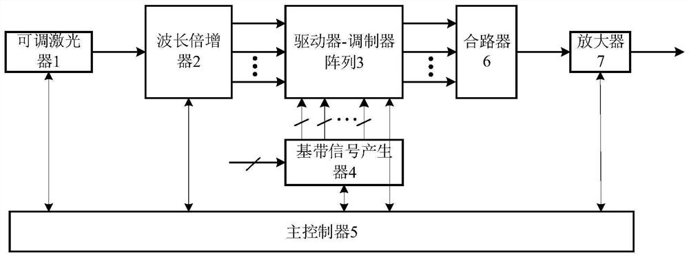
[0075] This embodiment provides a high-speed optical signal generating device, refer to figure 1 , the high-speed optical signal generating device includes: a tunable laser 1 , a wavelength multiplier 2 , a driver-modulator array 3 , a baseband signal generator 4 and a main controller 5 .
[0076] Wherein, the optical output end of the tunable laser 1 is connected to the optical input end of the wavelength multiplier 2, and the optical output end of the wavelength multiplier 2 is connected to the optical input end of the driver-modulator array 3, The electrical input of the driver-modulator array 3 is connected to the output of the baseband signal generator 4 . Wherein, the output optical power of the tunable laser 1 is not less than 15 dBm.
[0077] The control terminal of the wavelength multiplier 2 , the control terminal of the driver-modulator array 3 and the control terminal of the baseband signal generator 4 are respectively connected to the main controller 5 .
[0078...
Embodiment 2
[0122] Based on the high-speed optical signal generating device of the foregoing embodiment 1, this embodiment provides a control method of the high-speed optical signal generating device, through which the high-speed optical signal generating device is adjusted to output desired signals.
[0123] refer to Figure 8 , the control method of the high-speed optical signal generating device of the present embodiment includes the following steps:
[0124] Step 101: Drive the wavelength multiplier to convert the single-wavelength optical carrier generated by the tunable laser into 2N+1 optical carriers that are equally spaced and frequency-locked, and read the optical power P of the 2N+1 optical carrier 2N+1 .
[0125] Step 102: sequentially control the i-th wavelength bidirectional shifter, respectively obtain the optical power P2i of the 2i-th optical carrier and the optical power P2i-1 of the 2i-1-th optical carrier, according to the optical power P2i and the The relative magni...
Embodiment 3
[0138] to combine Figure 9 , to specifically illustrate the specific implementation process of the control method in the foregoing embodiment 2.
[0139] S1: Read setting parameters.
[0140] Wherein, the setting parameters include central wavelength, wavelength interval fs, number of wavelength channels 2N+1 and baud rate.
[0141] Wherein, the central wavelength may be 1550.12 nm, and the wavelength interval fs=50 GHz.
[0142] S2: Set the central wavelength and optical power of the tunable laser, turn on the tunable laser, set the delay of the optical path matcher to the pre-calibrated value, and read the optical power P corresponding to the 2N+1 optical carrier 2N+1 , set i=1.
[0143] S3: Turn on the optical amplifier in the 1st to N wavelength bidirectional shifter, and set the configuration parameters of 1 to N wavelength bidirectional shifter;
[0144] Wherein, the default gain of the optical amplifier in the first to N wavelength bidirectional shifters is set to ...
PUM
 Abstract
Description
Claims
Application Information
 - R&D
- Intellectual Property
- Life Sciences
- Materials
- Tech Scout
- Unparalleled Data Quality
- Higher Quality Content
- 60% Fewer Hallucinations
Browse by: Latest US Patents, China's latest patents, Technical Efficacy Thesaurus, Application Domain, Technology Topic, Popular Technical Reports.
© 2025 PatSnap. All rights reserved.Legal|Privacy policy|Modern Slavery Act Transparency Statement|Sitemap|About US| Contact US: help@patsnap.com


