Valve ball fixing device and shaft hole machining device

A technology for fixing devices and processing devices, applied in positioning devices, large fixed members, metal processing equipment, etc., can solve the problems of difficult fixing, irregular shape of C-type valve balls, poor processing of shaft holes, etc., to achieve convenience and speed Firmly fixed, reducing the difficulty of fixing, and improving the efficiency of opening holes

Inactive Publication Date: 2021-02-26
SHANDONG AFA FLOW CONTROL
View PDF8 Cites 0 Cited by
  • Summary
  • Abstract
  • Description
  • Claims
  • Application Information

AI Technical Summary

Problems solved by technology

[0004] Therefore, the technical problem to be solved by the present invention is to overcome the technical defects of the irregular shape of the C-type valve ball in the prior art, the difficulty in fixing, and the poor processing of the shaft hole, thereby providing a method for assisting in fixing the valve ball. Ball Fixture

Method used


Image

  • Valve ball fixing device and shaft hole machining device
  • Valve ball fixing device and shaft hole machining device
  • Valve ball fixing device and shaft hole machining device

Examples


Embodiment 1

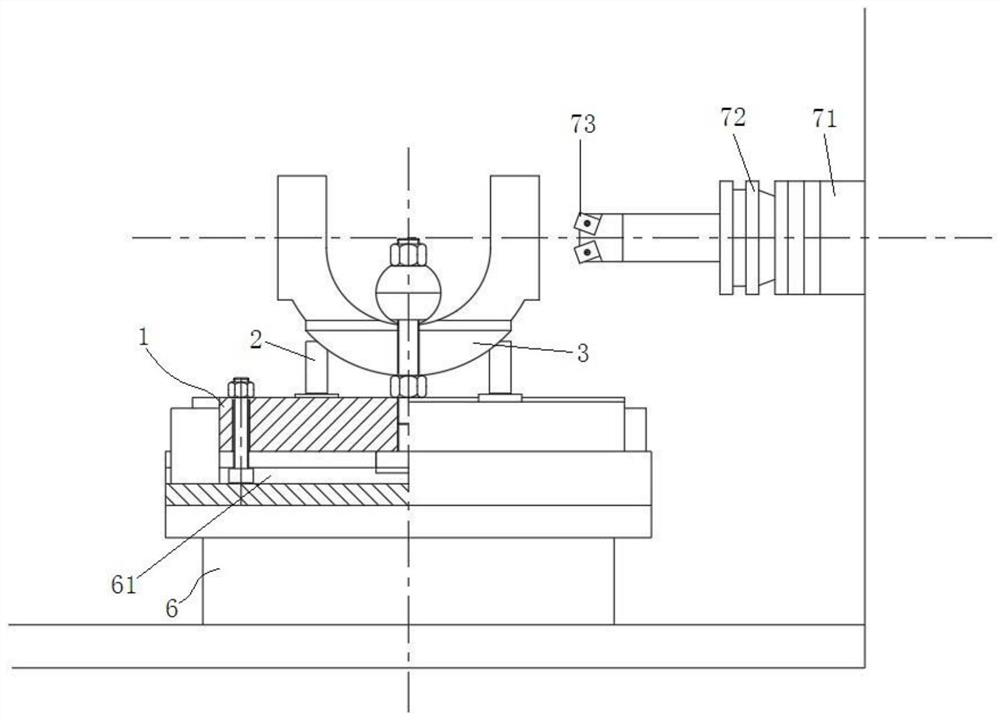
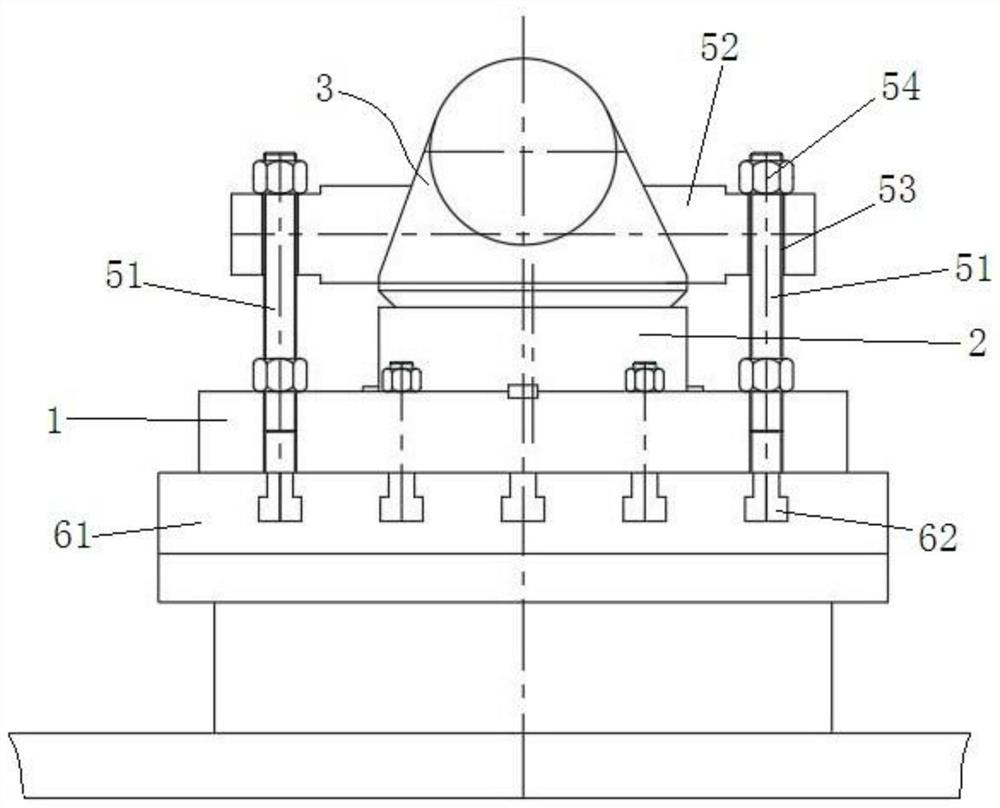
[0053] This embodiment provides a valve ball fixing device, refer to figure 1 As shown, it includes: a chassis 1, a support ring 2 and a press-down fixing structure; wherein the chassis 1 is suitable for being fixedly installed on the machine tool platform 61 of the machine tool 6, and the bottom of the support ring 2 is fixedly installed on the chassis 1 through the first installation structure, An arc-shaped concave ring is formed on the top of the support ring 2 for supporting the hemispherical surface of the C-shaped valve ball 3 .

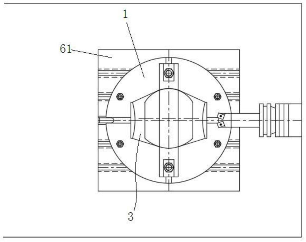
[0054] The position of C-type valve ball 3 after being fixed can refer to figure 2 As shown, the two parts of the C-type valve ball 3 that need to open shaft holes are distributed along the left and right directions in the figure, figure 2 The far right in the figure is the opening mechanism.

[0055] The structure of chassis 1 can refer to Figure 6 with Figure 7 As shown, the bottom of the chassis 1 is provided with a limit cylinder 1...

Embodiment 2

[0064] This embodiment provides a shaft hole processing device, such as figure 1 As shown, it includes a machine tool 6, a valve ball fixing device and an opening mechanism, wherein the valve ball fixing device is the valve ball fixing device described in Embodiment 1.

[0065] Such as image 3 with Figure 8 As shown, several inverted T-shaped through holes 62 are provided on the machine tool platform 61, and the fixed through holes 13 opposite to the inverted T-shaped through holes 62 are provided on the chassis 1, and the bolt assembly passes through the inverted T-shaped through holes 62 and fixed The through hole 13 is used to fix the chassis 1 on the machine tool platform 61 , and then fix the valve ball fixing device described in Embodiment 1 on the machine tool platform 61 .

[0066] The machine tool 6 can drive the machine tool platform 61 to do translational or rotational movements, so that the position where the shaft hole needs to be opened on the C-shaped valve ...


PUM


Abstract

The invention provides a valve ball fixing device and a shaft hole machining device. The valve ball fixing device comprises a bottom disc, a supporting ring and a pressing fixing structure, wherein the bottom disc is suitable for being fixed to a machine tool platform, the supporting ring is fixedly installed on the bottom disc, the top of the supporting ring is used for supporting a semi-spherical surface of a C-shaped valve ball, the pressing fixing structure is also fixedly installed on the bottom disc, the C-shaped valve ball is extruded in the direction from top to bottom, and extrusion fixing of the C-shaped valve ball is realized. According to the valve ball fixing device, firm fixing of the C-shaped valve ball can be conveniently and rapidly realized, preparation is made for shafthole forming operation in the next step, and therefore the fixing difficulty of the C-shaped valve ball can be lowered, and the hole forming efficiency can be improved.

Description

technical field [0001] The invention relates to the technical field of ball valve processing equipment, in particular to a valve ball fixing device and a shaft hole processing device with the valve ball fixing device. Background technique [0002] The C-type ball valve is a common opening and closing part, usually including a valve body, a valve ball, a valve stem and a driving device. Internally, the driving device drives the valve rod to drive the valve ball to rotate inside the valve body to open or close the fluid inlet and outlet. [0003] The C-type valve ball includes a hemisphere and a connecting portion connected to the hemisphere. A shaft hole needs to be opened on the connection portion for the valve stem to pass through, and the valve stem and the C-type valve ball are fixedly connected together. In order to ensure that the shaft hole matches the sealing surface of the hemisphere, the shaft hole is usually processed after the hemisphere is basically finished. At...

Claims


Application Information

Patent Timeline
Patent Type & Authority Applications(China)
IPC IPC(8): B23B41/00B23Q3/06B23Q1/25
CPCB23B41/00B23Q1/25B23Q3/062
Inventor 谢正泽朱志刚吴平叶友海黄亚光陈浩李增有张炎
Owner SHANDONG AFA FLOW CONTROL
Why Eureka
Try Eureka