Multifunctional machine tool workbench integrating electricity and machinery

A technology for multi-functional machine tools and workbenches, applied in metal processing machinery parts, manufacturing tools, metal processing equipment, etc., can solve problems such as wasted labor, single function of machine tool workbenches, and difficulty in maintenance and replacement of support legs, and achieve the solution function. Relatively simple, solve the effect of low security performance, and solve the effect of inconvenient movement

Inactive Publication Date: 2021-02-26
CHINA THREE GORGES UNIV
View PDF9 Cites 0 Cited by
  • Summary
  • Abstract
  • Description
  • Claims
  • Application Information

AI Technical Summary

Problems solved by technology

[0004] The purpose of the present invention is to provide a multifunctional machine tool workbench that integrates electricity and machinery to solve the problem that after the existing machine tool workbench is used for a period of time in the above-mentioned background technology, the supporting legs of the machine tool workbench are prone to wear and tear, thereby cause it to be damaged, and because most of the supporting legs of the machine tool table are integrally formed, it is difficult to repair and replace the supporting legs. In addition, due to the large volume and weight of the machine tool table, the volume and weight of the machine tool table Large movements are more troublesome, usually require a lot of labor, and are also more dangerous. At the same time, the function of the machine tool table is relatively single, and it cannot provide better protection when working, which will greatly reduce its safety. The problem

Method used


Image

  • Multifunctional machine tool workbench integrating electricity and machinery
  • Multifunctional machine tool workbench integrating electricity and machinery
  • Multifunctional machine tool workbench integrating electricity and machinery

Examples


Embodiment Construction

[0025] The following will clearly and completely describe the technical solutions in the embodiments of the present invention with reference to the accompanying drawings in the embodiments of the present invention. Obviously, the described embodiments are only some, not all, embodiments of the present invention. Based on the embodiments of the present invention, all other embodiments obtained by persons of ordinary skill in the art without making creative efforts belong to the protection scope of the present invention.

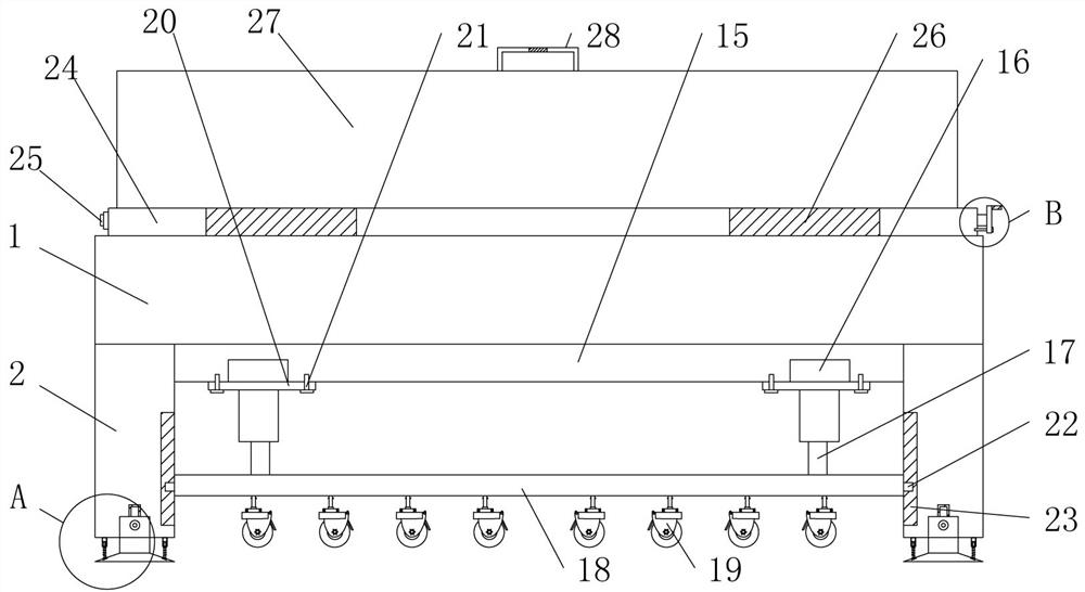
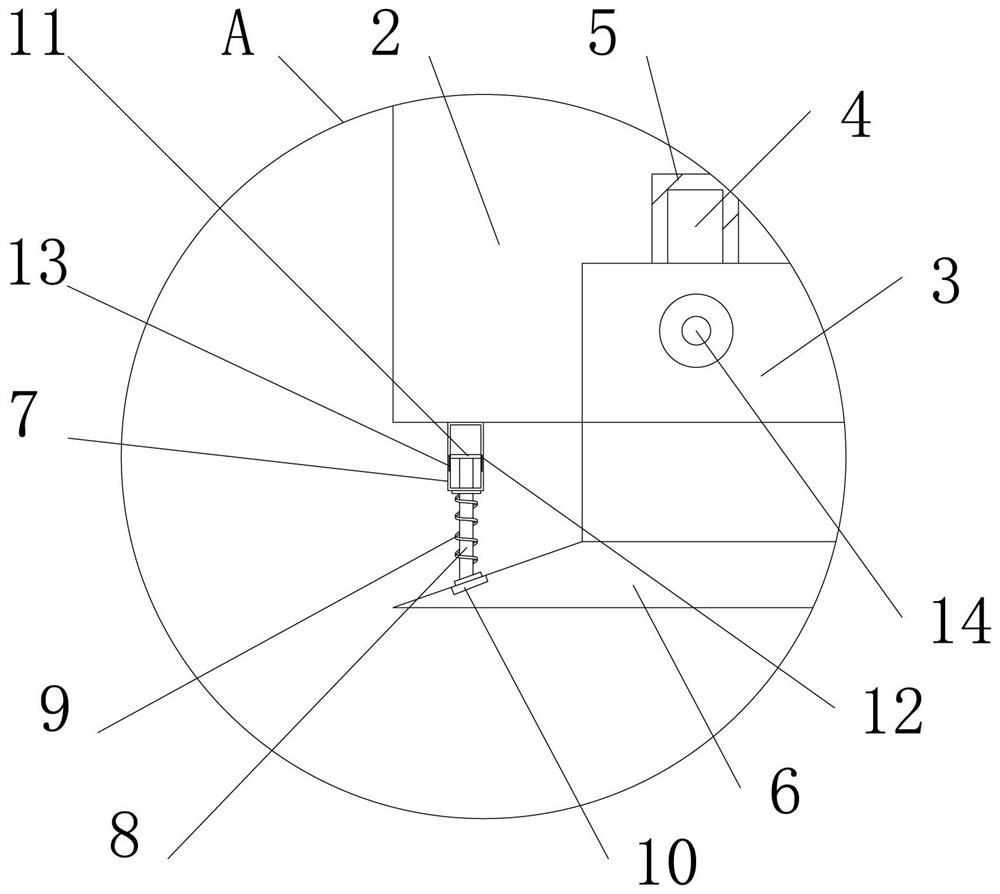
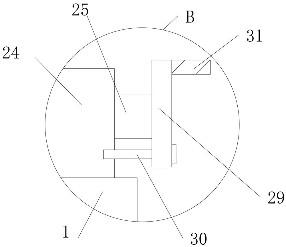
[0026] see Figure 1-5 , the present invention provides a technical solution: a multifunctional machine tool workbench integrating electricity and machinery, including a workbench body 1, four support legs 2 are fixedly connected to the four corners of the lower surface of the workbench body 1, and support The end of the leg 2 away from the workbench body 1 is fixedly sleeved with a connecting column 3, the top of the connecting column 3 is fixedly connected w...


PUM


Abstract

The invention discloses a multifunctional machine tool workbench integrating electricity and machinery, which comprises a workbench body. Four supporting legs are fixedly connected to the four cornersof the lower surface of the workbench body correspondingly; connecting columns are fixedly connected to the interiors of the ends, away from the workbench body, of the supporting legs in a sleeving mode; and the top ends of the connecting columns are fixedly connected with positioning rods; The device can be supported through the designed connecting columns and designed bottom blocks, and meanwhile, the bottom blocks are convenient to disassemble and replace through the arranged positioning rods, first positioning grooves and first fixing bolts, so that the practicability of the device is improved to a great extent; and through arranging external sleeve rods, built-in elastic rods, damping springs, clamping blocks and limiting blocks, the stability of the bottom blocks can be improved toa great extent, and the problem that when an existing device is used, the supporting legs are difficult to disassemble and replace after being abraded is solved.

Description

technical field [0001] The invention belongs to the technical field of electricity and machinery, and in particular relates to a multifunctional machine tool workbench integrating electricity and machinery. Background technique [0002] With the continuous development of science and technology, electrification and mechanization equipment continue to develop and improve. Among them, electricity is the collective name of disciplines or engineering fields such as the production, transmission, distribution, use, and electrical equipment manufacturing of electric energy. Technology as a means to create, maintain and improve a science of limited space and environment, covering three aspects of electric energy conversion, utilization and research, including basic theory, application technology, facilities and equipment, etc. Machine tool workbench is suitable for molds, fitters, testing , maintenance, assembly and other different applications, with good corrosion resistance, dirt r...

Claims


Application Information

Patent Timeline
Patent Type & Authority Applications(China)
IPC IPC(8): B23Q1/25B23Q1/01B23Q11/08B23Q11/00
CPCB23Q1/015B23Q1/25B23Q11/0032B23Q11/08
Inventor 徐启豪
Owner CHINA THREE GORGES UNIV
Why Eureka
Try Eureka