
Tank container frame structure

A technology of tank container and frame structure, which is applied in packaging, packaging recycling, transportation and packaging, etc. It can solve the problems of deformation, cracking, frame quality and poor force, so as to reduce material cost and maintenance cost and improve loading quality , the effect of light weight

Pending Publication Date: 2021-02-26
XI AN RAILWAY TRANSPORTATION EQUIP
View PDF0 Cites 1 Cited by
  • Summary
  • Abstract
  • Description
  • Claims
  • Application Information

AI Technical Summary

Problems solved by technology

[0003] Aiming at the defects and deficiencies in the prior art, the present invention provides a frame structure of a tank container, which solves the problem that the frame of the existing tank container is poorly stressed and easily leads to deformation and cracking and the frame quality is large

Method used


Image

  • Tank container frame structure

Examples


Embodiment 1

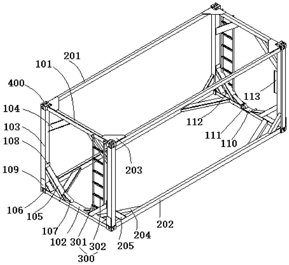
[0030] This embodiment provides a frame structure of a tank container, which includes two parallel and opposite square end frames and four parallel side beams connected between the two end frames, and the four side beams are all perpendicular to where the end frames are located. Plane and respectively located at the four corners of the end frame, the end frame and four side beams enclose a rectangular frame structure.

[0031] The end frame includes: an upper end beam 101 and a lower end beam 102 that are parallel and horizontal to each other, two corner columns 103 that are vertically connected between the upper end beam 101 and the lower end beam 102 and can form a square structure with the upper end beam 101 and the lower end beam 102, and The upper brace 104 between the upper end beam 101 and the corner post 103, the lower brace 105 between the lower end beam 102 and the corner post 103, the corner post brace 106 arranged at the junction of the lower end beam 102 and the co...


PUM


Abstract

The invention discloses a tank container frame structure which comprises two end frames and four side beams connected between the two end frames. Each of the end frames comprises an upper end beam, alower end beam, two corner posts, upper inclined struts, lower inclined struts, corner post inclined struts, lower inclined strut supplementary parts, lower inclined strut supplementary plates, and corner post supplementary plates. The upper end beam and the lower end beam are parallel to each other and are horizontal; the two corner posts are vertically connected between the upper end beam and the lower end beam and can form a square structure together with the upper end beam and the lower end beam; the upper inclined struts are arranged between the upper end beam and the corner posts; the lower inclined struts are arranged between the lower end beam and the corner posts; the corner post inclined struts arranged at the joints of the lower end beam and the corner posts; the lower inclinedstrut supplementary parts are arranged at the joint of the lower inclined struts and the lower end beam; the lower inclined strut supplementary plates are cushioned between the lower inclined struts and the corner posts; the corner post supplementary plates are arranged at the lower parts of the corner posts; each side beam comprises two upper side beams and two lower side beams; top protection plates are arranged at the joints of the upper side beams and the upper end beams; bottom inclined struts are arranged between the lower side beams and the lower end beams; and side inclined struts arearranged between the lower side beams and the corner posts. According to the tank container frame structure, basic transportation loading and unloading requirements of the tank container can be met, the structure stress effect is good, the weight is light, and the loading quality of the tank container is improved.

Description

technical field [0001] The invention relates to a tank container frame structure. Background technique [0002] As a kind of transportation equipment that can meet multimodal transportation, container plays an important role in the logistics and transportation industry. The frame structure is an important part of the tank container, and it also has a great influence on the container's loading and unloading intermodal operation, structural stress, and light weight. The existing tank container frame structure can meet the basic loading and unloading operations, but in the actual application process, it is found that the unreasonable design of the local structure leads to deformation and cracking, and the proportion of the frame mass is too large, resulting in a decrease in the container loading mass and an increase material cost. Contents of the invention [0003] Aiming at the defects and deficiencies in the prior art, the present invention provides a frame structure of a...

Claims


Application Information

Patent Timeline
Patent Type & Authority Applications(China)
IPC IPC(8): B65D88/12B65D90/20B65D90/08
CPCB65D88/128B65D88/129B65D90/20B65D90/08Y02W30/80
Inventor 徐远超朱英波李照明吕学鲁王淑霞李旭东
Owner XI AN RAILWAY TRANSPORTATION EQUIP
Learn More