Integrated stacking device for narrow space

A stacking device and space technology, which is applied in the field of stacking devices, can solve the problems that the stock cannot fully meet the production output demand, is difficult to realize, and wastes the space of the cargo space, so as to save the space requirement of the running device, control accurately, and build low cost effect

Inactive Publication Date: 2021-02-26
NANJING PANDA ELECTRONICS +1
View PDF4 Cites 1 Cited by
  • Summary
  • Abstract
  • Description
  • Claims
  • Application Information

AI Technical Summary

Problems solved by technology

[0002] At present, many factories are mainly used for the preparation and storage of raw materials of various types of products. With the continuous increase of scientific research and production tasks, the types of raw materials are gradually increasing, and the amount of raw materials is gradually increasing. The existing stock cannot fully meet the production demand.
Old factory buildings are generally narrow and need to store more raw materials in a warehouse with a certain floor area, but the three-dimensional automatic warehouse in conventional space consists of high-rise shelves, aisle-type large-height rail mobile stacker, conveying system, and automatic control system. To operate in such a narrow and high-height space, the stacker with large inertia needs to complete accurate positioning and stable start and stop, and the direction of the roadway track must have a certain buffer space, and the traditional parallel temporary storage equipment, so that a vertical row of cargo space needs to be vacated on the shelf, which wastes the limited space of the cargo space. Therefore, it is difficult to use the limited space in the length direction to place as many rows of shelves as possible.

Method used


Image

  • Integrated stacking device for narrow space
  • Integrated stacking device for narrow space
  • Integrated stacking device for narrow space

Examples


Embodiment Construction

[0016] Attached below Figure 1-6 The technical scheme of the present invention will be further described.

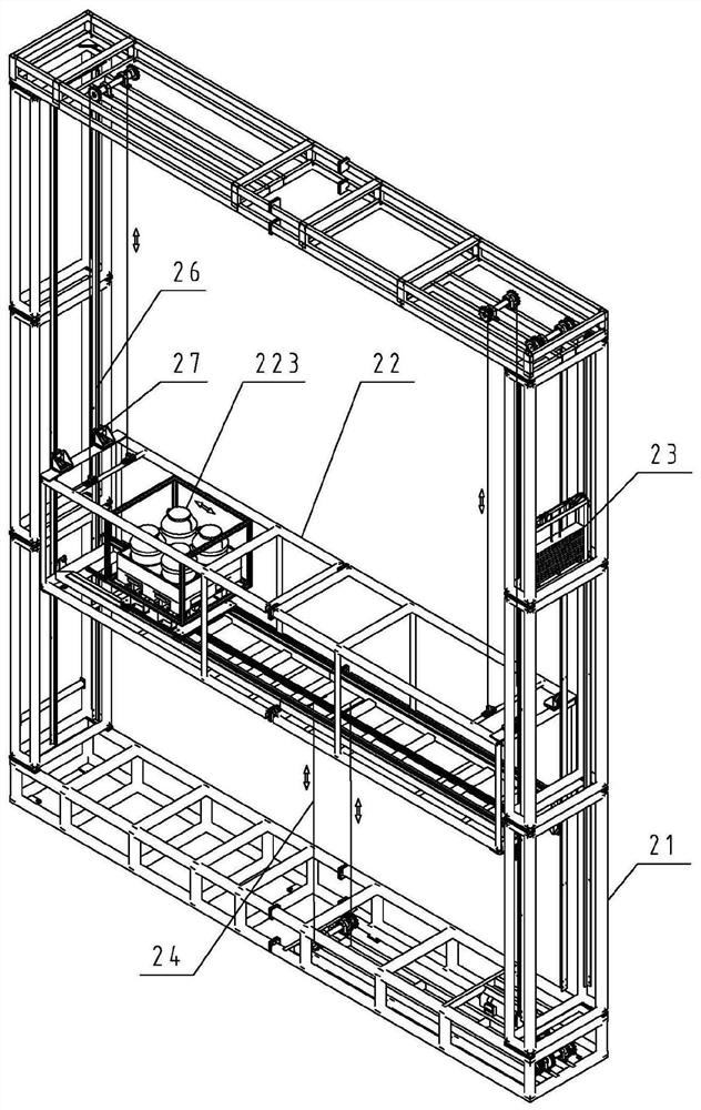
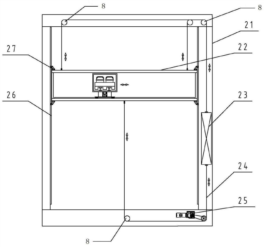
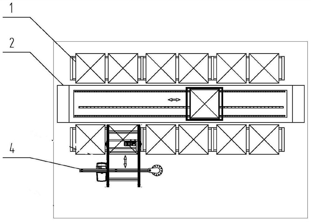
[0017] As shown in the figure, an integrated stacking device for a narrow space includes a shelf 1 arranged on both sides of the factory building, a stacker 2 located in the middle of the shelf 1, and a double stacker for moving goods in the stacker 2. Row guide rail 26 and the motor 25 that provides power for the stacking device, the frame 21 of stacker 2 is fixed on the ground, and the inside of stacker 2 is provided with the dolly 22 that is used for moving goods up and down, and the both sides of dolly 22 and vertical The double-row guide rails 26 arranged on both sides of the inside of the frame 21 are rollingly connected, the length direction of the bottom of the trolley 22 is provided with a linear guide rail 221, the trolley 22 is provided with a cargo fork 223 for containing goods, and the bottom of the shelf 1 is provided with for temporary storage and storage...


PUM


Abstract

The invention discloses an integrated stacking device for a narrow space. The integrated stacking device for the narrow space comprises goods shelves arranged on the two sides of a workshop, a stacking machine, double rows of guide rails located in the stacking machine and used for moving goods, and a motor. A frame of the stacking machine is fixed to the ground, and a trolley used for moving thegoods up and down is arranged in the stacking machine. The two sides of the trolley are in rolling connection with the double rows of guide rails vertically arranged on the two sides in the frame, a linear guide rail is arranged in the length direction of the bottom of the trolley, and a fork for containing the goods is arranged in the trolley. Temporary storage parts for temporarily storing and unloading the goods are arranged at the bottoms of the goods shelves and connected with a cantilever crane for taking out the goods. A fixed frame structure is adopted, the space requirement of a walking device is omitted, and the problems of large inertia and difficulty in start-stop control are solved. The arrangement of the temporary storage parts at the bottoms of the goods shelves changes a traditional parallel conveying mode, and the length space of the goods shelves is saved. The operation is stable, the construction cost is low, the control is accurate, and thus the narrow workshop haslarge capacity for storage.

Description

technical field [0001] The invention relates to a stacking device, in particular to an integrated stacking device used in a narrow space. Background technique [0002] At present, many factories are mainly used for the preparation and storage of raw materials of various types of products. With the continuous increase of scientific research and production tasks, the types of raw materials and the amount of raw materials are gradually increasing, and the existing stock cannot fully meet the production demand. Old factory buildings are generally narrow, and more raw materials need to be stored in a warehouse with a certain area. However, the three-dimensional automatic warehouse in conventional space consists of high-rise shelves, aisle-type large-height rail-mounted mobile stackers, conveying systems, and automated control systems. To operate in such a narrow and high-height space, the stacker with large inertia needs to complete precise positioning and stable start and stop, ...

Claims


Application Information

Patent Timeline
Patent Type & Authority Applications(China)
IPC IPC(8): B65G1/04B65G1/137B65G35/00
CPCB65G1/0492B65G1/1373B65G35/00
Inventor 安晨霞郭骥汪万元李松领
Owner NANJING PANDA ELECTRONICS
Why Eureka
Try Eureka