

Adsorbable and air-floatable device
An air flotation and air path technology, which is used in transportation and packaging, conveyor objects, furnaces, etc., can solve the problems of hard LCD glass screen, heavy LCD glass screen, and broken screen.
- Summary
- Abstract
- Description
- Claims
- Application Information
AI Technical Summary
Problems solved by technology
Method used
Image

Examples
Embodiment Construction
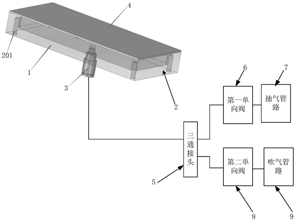
[0018] The core of the present invention is to provide an adsorbable and air-floatable device, which can realize the adsorption or suspension of items with different characteristics, and is compatible with the requirements of flipping and rotating LCD glass screens and OLED flexible screens, and will neither cause displacement of the LCD glass screen , without damaging the OLED flexible screen.
[0019] The following will clearly and completely describe the technical solutions in the embodiments of the present invention with reference to the accompanying drawings in the embodiments of the present invention. Obviously, the described embodiments are only some, not all, embodiments of the present invention. Based on the embodiments of the present invention, all other embodiments obtained by persons of ordinary skill in the art without making creative efforts belong to the protection scope of the present invention.
[0020] An embodiment of an adsorbable and air-floatable device p...
PUM
 Abstract
Description
Claims
Application Information