A method for preparing a multi-stage pre-embedded prefabricated component of a steel grouting sleeve connection joint

A technology for grouting sleeves and connecting joints, which is applied to building components, structural elements, building reinforcements, etc., can solve the problems of troublesome processing and installation, high cost, and the connection method of steel bars cannot meet the area percentage of lap joints of tension steel bars. , to achieve the effect of simple manufacturing process, low cost, improved seismic performance and anti-continuous collapse performance

Active Publication Date: 2022-04-29
HUNAN UNIV +1
View PDF8 Cites 0 Cited by
  • Summary
  • Abstract
  • Description
  • Claims
  • Application Information

AI Technical Summary

Problems solved by technology

Therefore, the reinforcement connection method of the semi-grouting sleeve of vertically stressed prefabricated concrete members such as prefabricated shear walls or frame columns cannot meet the requirements of my country's "Code for Design of Concrete Structures" GB50010 for tension reinforcement connections in the same connection section. Specified Requirements for Joint Area Percentage
[0003] Lap joints of tensile reinforcement are one of the difficult problems in the construction and processing of vertically stressed prefabricated components such as prefabricated shear walls or frame columns. ) using the half-grouting sleeve and the long sleeve to realize the dislocation connection of vertical steel bars. This method needs to process the connection between the half-grouting sleeve and the long sleeve. The long sleeve is directly embedded in the prefabricated shear wall. Processing and installation Alignment is troublesome and expensive

Method used


Image

  • A method for preparing a multi-stage pre-embedded prefabricated component of a steel grouting sleeve connection joint
  • A method for preparing a multi-stage pre-embedded prefabricated component of a steel grouting sleeve connection joint
  • A method for preparing a multi-stage pre-embedded prefabricated component of a steel grouting sleeve connection joint

Examples


Embodiment Construction

[0037] The detailed structure of the present invention will be further described below in conjunction with the accompanying drawings and specific embodiments.

[0038] A method for preparing a multi-stage pre-embedded prefabricated component of a steel bar grouting sleeve connection joint, comprising the following steps:

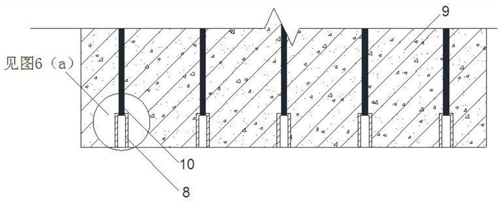
[0039] (1) table formwork is prepared, reinforcing bar 10 is set in table formwork;

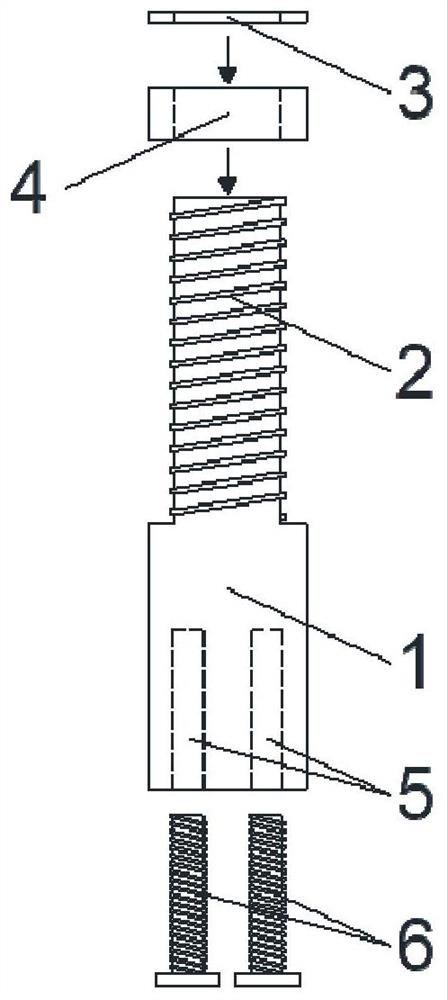
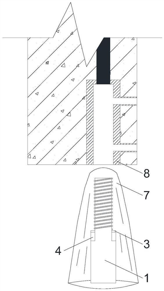
[0040] (2) Connect the grouting sleeve 8 at the bottom of the steel bar, set a magnetic guide sleeve at the bottom of part of the grouting sleeve 8 so that the positions of the grouting sleeve 8 are not at the same height, and stagger the pre-embedded grouting sleeve 8; the magnetic guide sleeve includes a guide sleeve Body, the guide cylinder body is divided into the guide cylinder lower part 1 and the guide cylinder upper connecting section 2, the outer diameter of the guide cylinder upper connecting section 2 is smaller than the outer diameter of the guide cylinder lower...


PUM


Abstract

The invention provides a method for preparing a multi-stage pre-embedded prefabricated component of a steel bar grouting sleeve connection joint, comprising the following steps: preparing a table formwork, setting a steel bar (10) in the table formwork; connecting a grouting sleeve (8) at the bottom of the steel bar ), set a magnetic guide sleeve at the bottom of part of the grouting sleeve (8) so that the position of the grouting sleeve (8) is not at the same height, and stagger the pre-embedded grouting sleeve (8); after the pre-embedded position of the grouting sleeve (8) is set, Concrete is poured; after the concrete is solidified, the magnetic guide cylinder is pulled out, and the bottom of the grouting sleeve (8) forms a cavity communicating with the outside to obtain a multi-stage pre-embedded prefabricated component of the steel grouting sleeve connection joint, and the magnetic guide cylinder is recycled. The method can well realize the vertical dislocation connection of the prefabricated shear wall, and meets the specified requirements, and the construction method is simple, the disassembly is convenient, and the magnetic guide cylinder can be recycled.

Description

technical field [0001] The invention relates to the field of prefabricated buildings, in particular to a method for preparing multi-stage pre-embedded prefabricated components of steel bar grouting sleeve connection joints. Background technique [0002] my country's "Code for Design of Concrete Structures" GB50010 requires the reinforcement connection of reinforced concrete structures to require the percentage of the lap joint area of ​​tension reinforcement in the same connection section as follows: for wall members, it should not be greater than 25%; for column members, it should not be More than 50%, the joints of walls, columns and prefabricated components can be appropriately relaxed. At present, the semi-grouting sleeve connection steel bar joints of prefabricated vertical prefabricated concrete members are generally pre-buried and arranged in the same connection section of the frame column or shear (seismic) wall of the vertical prefabricated member. , especially unde...

Claims


Application Information

Patent Timeline
Patent Type & Authority Patents(China)
IPC IPC(8): E04C5/16
CPCE04C5/16
Inventor 唐昌辉
Owner HUNAN UNIV
Why Eureka
Try Eureka