
Pipe clamp valve
A pipe pinch valve and valve body technology, applied in the direction of diaphragm valves, valve devices, engine components, etc., can solve the problems of hidden safety hazards, pollution, and high wear rate of lining pipes, and achieve the effect of guaranteeing safety and reliability.
- Summary
- Abstract
- Description
- Claims
- Application Information
AI Technical Summary
Problems solved by technology
Method used
Image

Examples
Embodiment Construction
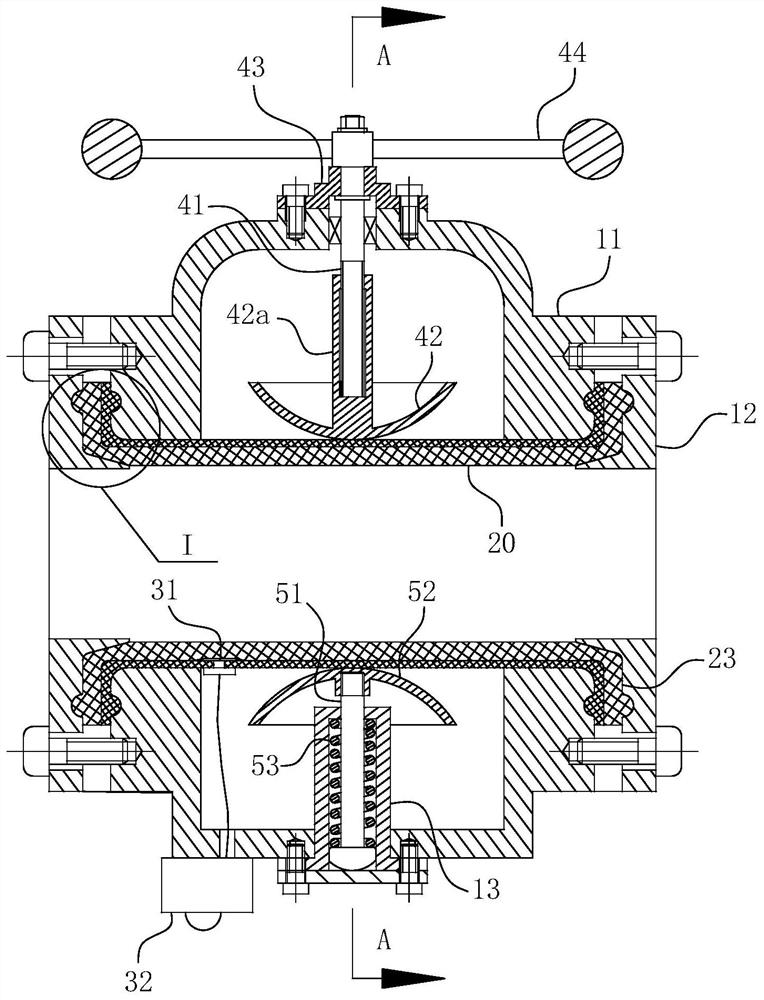
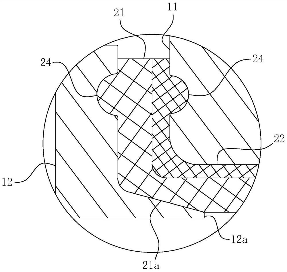
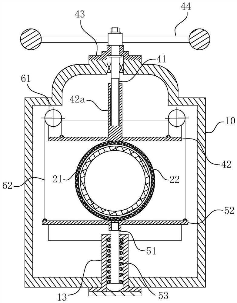
[0037] For ease of understanding, combined here Figure 1-4 , the concrete structure and working mode of the present invention are further described as follows:
[0038] The specific structure of the present invention is as Figure 1-4As shown, the main structure includes a valve body 10, a switch part, a flow pipe 20 and a reversing assembly. Among them: the valve body 10 includes the middle valve pipe 11 and the flange end caps 12 which are located at both ends and form a flange fit; the flow pipe 20 consists of a liner pipe 21 as the inner casing and a protective pipe as the outer casing. 22 together constitute. The direction-changing assembly includes a traction rope 62 and a direction-changing wheel 61 to realize the synchronous movement of the power plate 42 at the upper pressing assembly and the follower plate 52 at the lower pressing assembly toward and away from each other.
[0039] Specific to figure 1 In the shown structure, it can be seen that: the two ends of ...
PUM
 Abstract
Description
Claims
Application Information