
Crankshaft journal cone angle detection device and using method thereof

A technology of angle detection and crankshaft journal, which is applied in the field of auto parts manufacturing, can solve the problems of low measurement accuracy of measurement methods, inability to use online detection of three coordinates, large detection errors, etc., and achieve simple structure, online and rapid detection, Simple operation effect

Pending Publication Date: 2019-11-12
桂林福达曲轴有限公司
View PDF0 Cites 2 Cited by
  • Summary
  • Abstract
  • Description
  • Claims
  • Application Information

AI Technical Summary

Problems solved by technology

[0003] At present, the conventional detection of the cone angle is to use the three-coordinate detection, or usually use the indirect detection method of coloring. The method is to first uniformly coat a thin layer of red lead on the entire length of the processed journal cone angle. , and then put a standard taper hub on the journal, and turn the standard taper hub slightly, then remove the standard taper hub, and visually check whether the taper angle of the journal is painted red and whether there is any trace of contact with the inner hole of the standard taper hub , Whether it is fully matched, this method has a large detection error, especially when the thickness of the red lead is not well grasped, it will directly affect the detection result, instead of directly detecting the cone angle, the measurement method has low measurement accuracy and is affected by human factors Larger, and the three coordinates cannot be used for online detection

Method used


Image

  • Crankshaft journal cone angle detection device and using method thereof
  • Crankshaft journal cone angle detection device and using method thereof
  • Crankshaft journal cone angle detection device and using method thereof

Examples


Embodiment 1

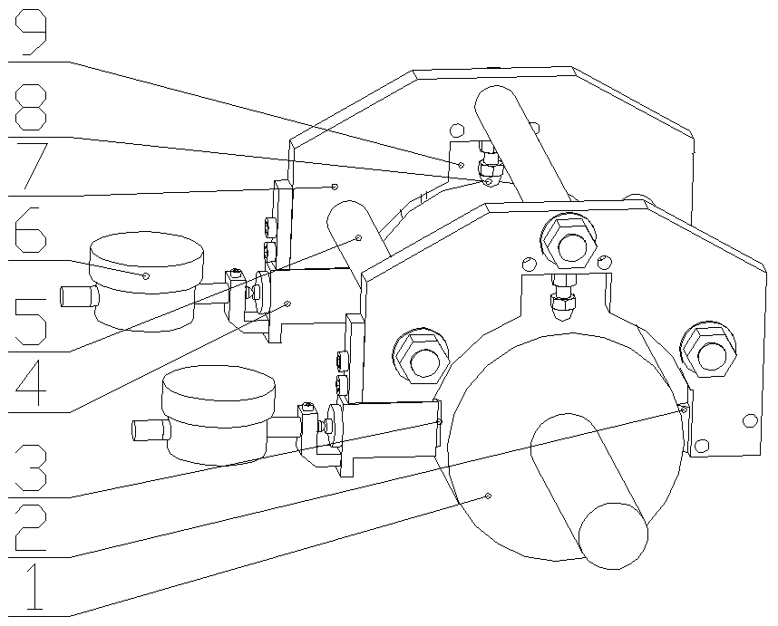
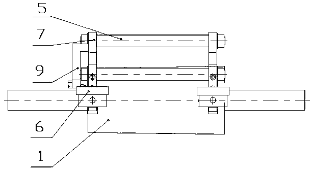
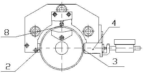
[0025] Such as Figure 1-3 As shown, a crankshaft journal cone angle detection device is mainly composed of two positioning plates 7, two gauge frames 4 and two dial gauges 6; the gauge frame 4 is fixedly mounted on the front end side of the positioning plate 7 above; the dial indicator 6 is fixedly installed on the meter frame 4; the positioning plate 7 is symmetrically arranged, and is fixedly installed together through three connecting rods 5, and the three connecting rods 5 are symmetrically and evenly arranged in the center and installed on two Between the block positioning plates 7; the positioning plate 7 is opened from the bottom, and a quasi-circular groove is set; three fulcrums are arranged on the groove surface of the quasi-circular groove, which are respectively arranged on the quasi-circular groove. The adjustable fulcrum 8 on the top, the movable fulcrum 3 arranged on the side of the table frame and having a radial preload, and the fixed fulcrum 2 arranged on th...

Embodiment 2

[0027] A crankshaft journal cone angle detection device, mainly composed of two positioning plates 7, two gauge frames 4 and two dial gauges 6; the gauge frame 4 is fixedly mounted on the front end side of the positioning plate 7; The above-mentioned dial indicator 6 is fixedly installed on the meter frame 4; the above-mentioned positioning plate 7 is symmetrically arranged, and is fixedly installed together through four connecting rods 5, and the four connecting rods 5 are symmetrically and evenly arranged in the center and installed on two positioning plates 7; the positioning plate 7 is opened from the bottom, and a quasi-circular groove is set; three fulcrums are arranged on the groove surface of the quasi-circular groove, which are respectively arranged on the top of the quasi-circular groove. The fulcrum 8, the movable fulcrum 3 arranged on the side of the watch frame and having a radial preload force, and the fixed fulcrum 2 arranged on the opposite side of the movable f...


PUM


Abstract

The invention discloses a crankshaft journal cone angle detection device and a using method thereof. The detection device is mainly composed of two positioning plates, two dial gauge stands and two dial gauges; the dial gauge stands are fixedly installed on the front end side surface of the positioning plate; the dial gauges are fixedly installed on the dial gauge stands; the positioning plates are symmetrically arranged and fixedly installed together through a connecting rod; each positioning plate is open from the bottom, and provided with a quasi-circular groove; three supporting points arearranged on the groove surface of the quasi-circular groove and are respectively an adjustable supporting point arranged at the top of the quasi-circular groove, a movable supporting point arranged on the side of the dial gauge stands and has the pressing preload in the radial direction, and a fixed supporting point arranged on the opposite side of the movable supporting point; and an axial positioning block is further disposed on the outer side surface of one of the positioning plates. The device disclosed by the invention is simple in structure, small in measurement error and high in precision, can be used for rapidly and effectively detecting an angle line value of the journal cone angle, can realize online detection control, and the detection method is simple to operate and not influenced by human factors.

Description

technical field [0001] The invention belongs to the technical field of auto parts manufacturing, and relates to the machining of an automotive engine crankshaft, in particular to a crankshaft journal cone angle detection device and a use method thereof. Background technique [0002] The crankshaft is a key component of the transmission system of the internal combustion engine. During the working process, the thrust of the connecting rod is converted into a rotational force, thereby generating torque, and the heat energy generated by fuel combustion is converted into mechanical energy of mechanical rotation through the crank connecting rod mechanism. By assembling parts that transmit torque at the front and rear ends, the flywheel, torsional damper, pulley, timing gear, etc. are driven to drive other auxiliary devices. Part of the power output journal is designed with a conical structure, which is used for static fit and precise positioning. Using the principle of friction, a...

Claims


Application Information

Patent Timeline
Patent Type & Authority Applications(China)
IPC IPC(8): G01B5/24G01B5/20
CPCG01B5/24G01B5/201G01B5/003
Inventor 易丽群夏志成粟奕勇
Owner 桂林福达曲轴有限公司
Learn More