Eureka AIR delivers breakthrough ideas for toughest innovation challenges, trusted by R&D personnel around the world.

Damping type oil pump support

A technology of oil pump and support, which is applied in the field of shock-absorbing oil pump support, can solve the problems of shortening the service life of the oil pump and damage to the oil pump body, and achieve the effects of increasing applicability, shortening service life and tight vibration

Pending Publication Date: 2021-02-26
ZHEJIANG OCEAN UNIV
View PDF5 Cites 0 Cited by
  • Summary
  • Abstract
  • Description
  • Claims
  • Application Information

AI Technical Summary

Problems solved by technology

[0004] The current oil pump will produce a certain vibration during operation. If it is not controlled for a long time, it will cause damage to the oil pump body and shorten the service life of the oil pump. Therefore, a shock-absorbing oil pump support is needed

Method used


Image

  • Damping type oil pump support
  • Damping type oil pump support
  • Damping type oil pump support

Examples


Embodiment 1

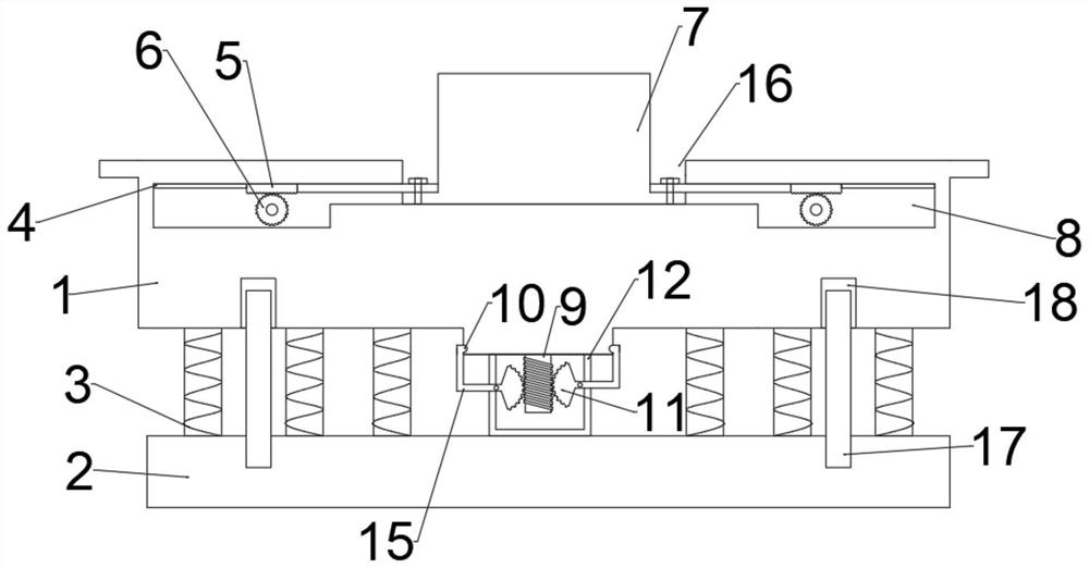
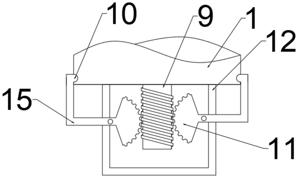
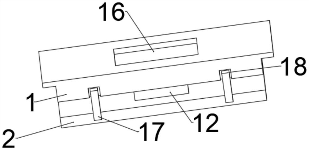
[0028] refer to Figure 1 ~ Figure 3 , a shock-absorbing oil pump support, including a bottom plate 2, a support box 12 is connected with bolts above the bottom plate 2, a placement plate 1 is bolted on the side of the support box 12 away from the bottom plate 2, and a fixing plate is provided above the placement plate 1. Cavity 16, the oil pump 7 is connected with the bolts in the fixed cavity 16, and the interior of the support box 12 is provided with a shock absorbing mechanism, which includes a screw rod 9, a clamping head 10, a sector gear 11 and a connecting rod 15, placed under the plate 1 The screw rod 9 is connected to the center bolt, and the screw rod 9 runs through the upper shell wall of the support box 12. The left and right sides of the screw rod 9 are meshed with a sector gear 11, and the end of the sector gear 11 away from the screw rod 9 is bolted to a connecting rod. 15. The end of the connecting rod 15 close to the sector gear 11 is rotatably connected to t...

Embodiment 2

[0034] refer to Figure 4 , a shock-absorbing oil pump support. Compared with Embodiment 1, this embodiment is provided with a cover plate 13 above the placement plate 1, and one end of the cover plate 13 close to the oil pump 7 is connected with a connecting block 14 by bolts. The connecting block 14 It is connected with the oil pump 7 by bolts, and the end of the cover plate 13 away from the oil pump 7 is bolted to a clamping plate 19. The clamping plate 19 and the upper boss of the placement plate 1 are embedded and connected. When the oil pump 7 is placed in the fixed cavity 16, the clamping The plate 19 and the upper boss on which the plate 1 is placed are embedded with each other, and then the connecting block 14 is fixedly connected with the oil pump 7 to limit the position of the oil pump 7, so that the shock absorption effect is better and its applicability is increased.

[0035] Working principle: when the oil pump 7 is put into the fixed cavity 16, the position of t...


PUM


Abstract

The invention discloses a damping type oil pump support. The support comprises a bottom plate, wherein a supporting box is arranged above the bottom plate, a containing plate is arranged on the side,away from the bottom plate, of the supporting box, a fixing cavity is formed above the containing plate, an oil pump is arranged in the fixing cavity, a damping mechanism is arranged in the supportingbox, the damping mechanism comprises a lead screw, a clamping head, sector gears and connecting rods, the lead screw is arranged in the center of the lower portion of the containing plate and penetrates through the upper side shell wall of the supporting box, the sector gears are arranged on the left side and the right side of the lead screw, and the connecting rods are arranged at the ends, awayfrom the lead screw, of the sector gears. According to the support, the oil pump is placed in the fixing cavity to be fixed, certain vibration can be generated, movement of the containing plate in the left-right direction is limited, the lead screw can move downwards along with the containing plate, then the sector gear swings to generate upward force on the connecting rods, the clamping head andthe groove are connected more tightly in an embedded mode, and the more vibration is, the tighter the clamping head and the groove are, so that the damping effect is achieved, and the support is suitable for large-scale popularization.

Description

technical field [0001] The invention relates to the technical field of oil pumps, in particular to a shock-absorbing oil pump support. Background technique [0002] The oil pump is a light and compact pump, which can be divided into three categories: inline type, distribution type and single type. The oil pump needs a power source to run, and the camshaft at its lower part is driven by the crankshaft gear of the engine. [0003] Oil pump An oil pump with a housing made of aluminium-containing material and a movable molded part arranged in the housing, wherein the movable molded part is at least partially made of a sinterable, is made of a material comprising at least one austenitic iron-based alloy, and wherein the molding made of a sinterable material has a coefficient of thermal expansion that is at least 60% of the coefficient of thermal expansion of the housing. [0004] The current oil pump will vibrate to a certain extent during operation. If it is not controlled for...

Claims


Application Information

Patent Timeline
IPC IPC(8): F16M11/22F16M11/04F16F15/067F04B53/00
CPCF16M11/22F16M11/04F16F15/067F04B53/003
Inventor 王雪林佳胡家希
Owner ZHEJIANG OCEAN UNIV
Why Eureka
Eureka Blog
Learn More