Eureka AIR delivers breakthrough ideas for toughest innovation challenges, trusted by R&D personnel around the world.

Transcranial shear wave brain tissue viscoelasticity imaging device

An imaging device and shear wave technology, applied in the directions of ultrasonic/sonic/infrasonic image/data processing, acoustic diagnosis, infrasonic diagnosis, etc., can solve problems such as limited application, large sound attenuation coefficient, and difficulty in focusing, so as to improve imaging Effect, reduce vibration noise, increase the effect of contact area

Active Publication Date: 2021-01-05
XI AN JIAOTONG UNIV
View PDF8 Cites 2 Cited by
  • Summary
  • Abstract
  • Description
  • Claims
  • Application Information

AI Technical Summary

Problems solved by technology

However, due to limiting factors such as inconsistent skull density, uneven thickness, irregular shape, and large sound attenuation coefficient, the traditional shear wave generator based on externally excited vibration cannot ensure that the shear wave in the appropriate parameter range can be generated regularly. Transcranial ultrasonic shear wave brain tissue viscoelastic imaging cannot guarantee the necessary prerequisites
[0006] However, the ultrasonic shear wave viscoelastic imaging technology based on the acoustic radiation force must directly act on the biological tissue with focused ultrasound. This technique has the limitation of difficulty in focusing under transcranial conditions and the safety of high-power focused ultrasound on brain tissue. Sexuality remains unclear
These limit the application of ultrasonic shear wave elastography based on acoustic radiation force in transcranial conditions
[0007] In summary, the existing viscoelastic imaging technology still has great limitations for the early diagnosis and pathological research of transcranial brain tissue. The development of a safe and effective transcranial ultrasonic shear wave brain tissue viscoelastic imaging device is particularly important important

Method used


Image

  • Transcranial shear wave brain tissue viscoelasticity imaging device
  • Transcranial shear wave brain tissue viscoelasticity imaging device
  • Transcranial shear wave brain tissue viscoelasticity imaging device

Examples


Embodiment Construction

[0029] The present invention will be further described in detail below in conjunction with the accompanying drawings, which are explanations rather than limitations of the present invention.

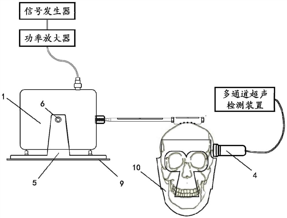
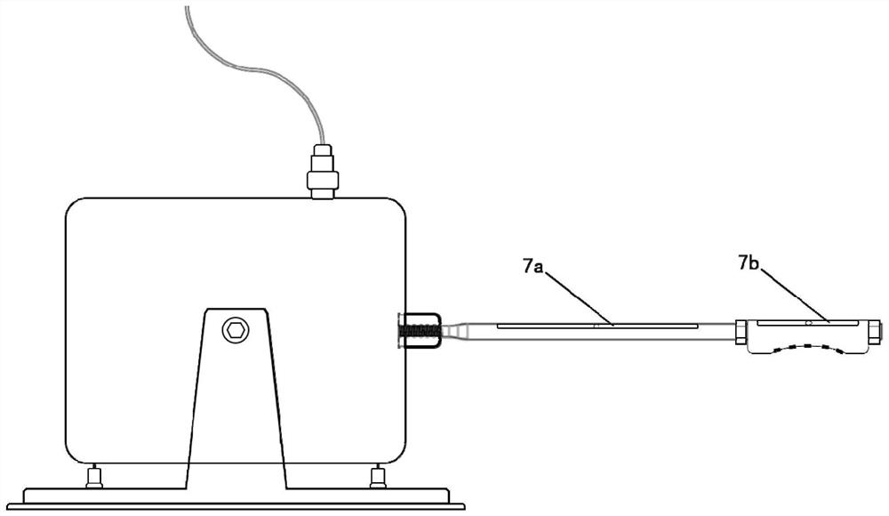
[0030] Such as Figure 1-4 As shown, a transcranial shear wave brain tissue viscoelastic imaging device includes a transcranial vibration generating device, a multi-channel ultrasonic device, a vibrating rod 2, a transcranial vibration direction control device, and a transcranial vibration monitoring device.

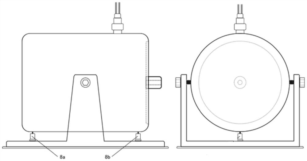
[0031] The transcranial vibration generating device includes a signal generator, a power amplifier and a vibration exciter 1 connected in sequence. The vibration exciter 1 is supported on a bracket and can be adjusted in level.

[0032] One end of the vibrating rod 2 is connected to the vibrating instrument 1 through an M5 thread, and the other end of the vibrating rod 2 is set with a flexible plate 3, and the two ends of the flexible plate 3 are fixed on the vibrating rod 2 by bol...


PUM


Abstract

The invention discloses a transcranial shear wave brain tissue viscoelasticity imaging device which comprises a transcranial vibration generating device, an ultrasonic generator, a vibrating rod, a monitoring device, an adjusting device and a damping support. Shear waves can be regularly transmitted into the brain tissue through the skull, so that transcranial shear wave brain tissue viscoelasticity detection is realized. Secondly, a vibration exciter, the vibrating rod and a flexible plate are adjusted to be in a horizontal state through the adjusting device to control the shear waves to be vertically propagated, quantitative accurate control is conducted on the generation and propagation law of the shear waves, the propagation of the shear waves can be parallel to each ultrasonic scanning line, then the shear wave velocity of each scanning line is accurately worked out, and then two-dimensional shear wave viscoelasticity imaging is conducted, so that the problem that only the shear wave average velocity can be worked out along central axis ultrasonic scanning lines in traditional externally excited vibration is solved.

Description

technical field [0001] The invention relates to the technical field of medical ultrasonic imaging, in particular to a transcranial shear wave brain tissue viscoelastic imaging device. Background technique [0002] The viscoelasticity and other mechanical properties of brain tissue are of great value to the pathological research of related diseases. Early diagnosis of diseases such as Alzheimer's disease and hydrocephalus can be realized through the detection of brain tissue viscoelasticity. At present, most of the studies on the elastic characteristics of brain tissue choose to use magnetic resonance technology, that is, magnetic resonance elastography (MRE), but this technology inevitably has limitations such as complicated operation, high cost, and slow imaging speed. [0003] In comparison, ultrasonic shear wave elastography (SWE) has developed rapidly in recent years, which solves the above limitations in principle and has stronger practicability. At present, ultrasonic...

Claims


Application Information

Patent Timeline
Patent Type & Authority Applications(China)
IPC IPC(8): A61B8/08
CPCA61B8/485A61B8/0808
Inventor 万明习于建军郭昊张红梅路舒宽
Owner XI AN JIAOTONG UNIV
Why Eureka
Eureka Blog
Learn More