Installation structure facilitating maintenance of central air conditioner

A central air conditioner and installation structure technology, which is applied in the field of installation structure, can solve problems such as inconvenient maintenance work, trouble, damage to the central air conditioner, etc., and achieve the effect of convenient installation and disassembly

Active Publication Date: 2021-02-26
广州奥揽达节能科技有限公司
View PDF17 Cites 0 Cited by
  • Summary
  • Abstract
  • Description
  • Claims
  • Application Information

AI Technical Summary

Problems solved by technology

The principle of liquid vaporization refrigeration is used to provide the required cooling capacity for the air conditioning system to offset the heat load of the indoor environment; the heating system provides the required heat for the air conditioning system to offset the cooling and heating load of the indoor environment. The refrigeration system is the central The most important part of the air-conditioning system, its type, operation mode, and structural form directly affect the economy, efficiency, and rationality of the central air-conditioning system in operation. The central air-conditioning internal unit is an important part of the central air-conditioning system , is installed indoors for heating and cooling purposes. When the central air conditioner in the prior art is installed, the central air conditioner is connected to the bracket through bolts, and then the bracket is fixed on the wall. This installation method, It is inconvenient to disassemble, and it is easy to cause damage to the central air conditioner during installation. When there is a problem with the central air conditioner, it is inconvenient to disassemble, which brings inconvenience to maintenance work, and the air outlet plate installed at the air outlet of the existing central air conditioner During long-term use, a large amount of dust and bacteria are likely to be generated, which needs to be cleaned. However, most of the existing methods are manually wiped by the staff, which is very troublesome.

Method used


Image

  • Installation structure facilitating maintenance of central air conditioner
  • Installation structure facilitating maintenance of central air conditioner
  • Installation structure facilitating maintenance of central air conditioner

Examples


Embodiment Construction

[0029] The following will clearly and completely describe the technical solutions in the embodiments of the present invention with reference to the accompanying drawings in the embodiments of the present invention. Obviously, the described embodiments are only some, not all, embodiments of the present invention. Based on the embodiments of the present invention, all other embodiments obtained by persons of ordinary skill in the art without making creative efforts belong to the protection scope of the present invention.

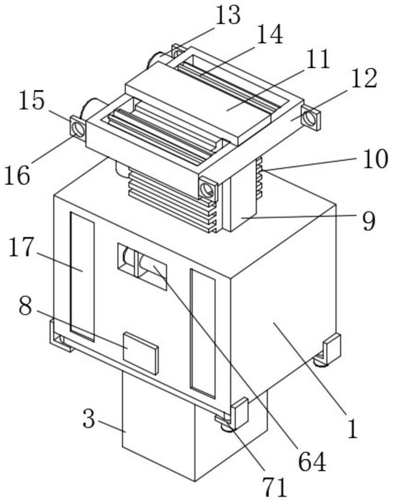
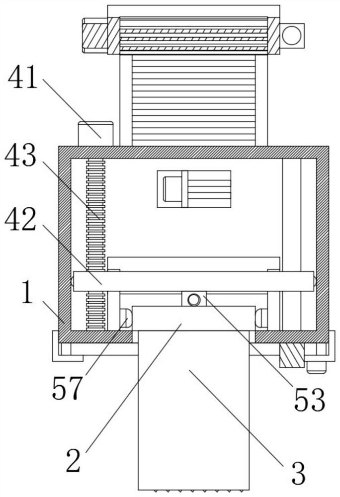
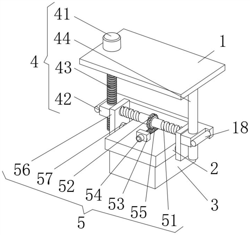
[0030] see Figure 1-5 The present invention provides a technical solution: an installation structure for central air-conditioning maintenance, including an installation box 1, a moving assembly 4, a fixing assembly 5, a supporting assembly 6 and a conveying assembly 7;

[0031]Installation box 1: There is an installation board 2 inside, two corresponding card slots are opened on the left and right sides of the installation board 2, and the central air conditi...


PUM


Abstract

The invention discloses an installation structure facilitating maintenance of a central air conditioner. The installation structure comprises an installation box, a moving assembly, a fixing assembly,a supporting assembly and a conveying assembly; an installation plate is arranged in the installation box, two corresponding clamping grooves are formed in the left side and the right side of the installation plate, and a central air conditioner body is fixed to the lower side face of the installation plate; and the moving assembly comprises a first motor, a moving frame, a threaded rod and a limiting rod, the first motor is mounted on the upper side face of the installation box, the moving frame is arranged in the installation box, a threaded through groove is formed in the left side edge ofthe moving frame, the interior of the threaded through groove is in threaded connection with the threaded rod, and the upper end of the threaded rod is connected with an output shaft of the first motor so that the central air conditioner can be installed and detached conveniently, the height of the central air conditioner can be adjusted, and an air outlet plate can be cleaned conveniently.

Description

technical field [0001] The invention relates to the technical field of central air-conditioning, in particular to an installation structure for central air-conditioning maintenance. Background technique [0002] The central air-conditioning system consists of one or more cold and heat source systems and multiple air-conditioning systems. This system is different from traditional refrigerant air-conditioning systems (such as single-body units, VRV) to centrally process air to meet comfort requirements. The principle of liquid vaporization refrigeration is used to provide the required cooling capacity for the air conditioning system to offset the heat load of the indoor environment; the heating system provides the required heat for the air conditioning system to offset the cooling and heating load of the indoor environment. The refrigeration system is the central The most important part of the air-conditioning system, its type, operation mode, and structural form directly affe...

Claims


Application Information

Patent Timeline
Patent Type & Authority Applications(China)
IPC IPC(8): F24F13/32
CPCF24F13/32
Inventor 吴敏娜
Owner 广州奥揽达节能科技有限公司
Why Eureka
Try Eureka