
Drying device, garbage treatment device and material machining method

A drying device and discharge port technology, which is applied in the direction of drying solid materials, drying, drying machines, etc., can solve problems such as waste, insufficient power, and reduced drying stability, and achieve low equipment cost and use cost, Ease of processing and high integration

Pending Publication Date: 2021-02-26
环川环保设备(苏州)有限公司
View PDF12 Cites 4 Cited by
  • Summary
  • Abstract
  • Description
  • Claims
  • Application Information

AI Technical Summary

Problems solved by technology

The current drying equipment, such as the structure disclosed in the application number 201520058535, uses a single screw conveying shaft to transport materials and realize heat conduction through a heat medium (oil or water). The single screw conveying structure is used for solid-liquid When transporting separated and pulverized food waste solids with certain humidity and viscosity, there is often insufficient power, resulting in reduced drying stability
[0006] In addition, oil and water are used to conduct heat to the U-shaped panel wall to realize heating. When drying, the oil and water need to be heated first to realize the heating of the U-shaped panel wall. It needs two heat conductions, which increases the heating time and The loss of heat conduction, and a certain amount of water, oil and other resources need to be wasted, which increases the drying cost and also increases the complexity of the equipment structure

Method used

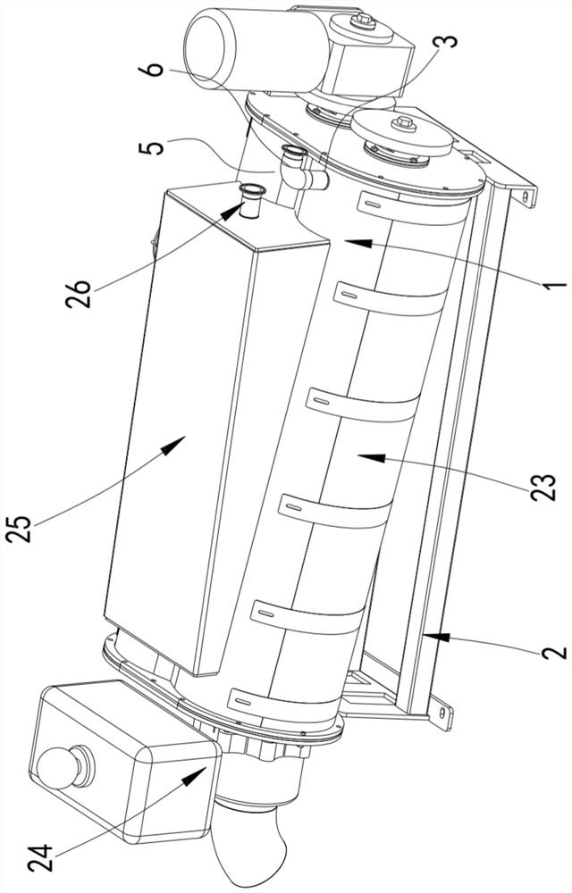
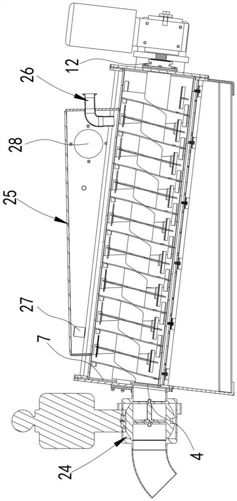
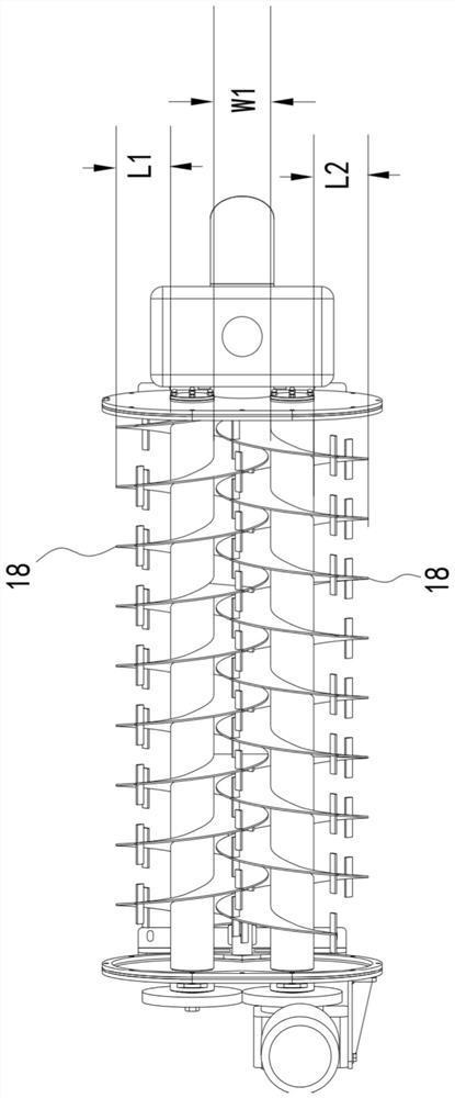

Image

  • Drying device, garbage treatment device and material machining method
  • Drying device, garbage treatment device and material machining method
  • Drying device, garbage treatment device and material machining method

Examples


Embodiment Construction

[0051] Objects, advantages and features of the present invention will be illustrated and explained by the following non-limiting description of preferred embodiments. These embodiments are only typical examples of applying the technical solutions of the present invention, and all technical solutions formed by adopting equivalent replacements or equivalent transformations fall within the protection scope of the present invention.

[0052]In the description of the scheme, it should be noted that the terms "center", "upper", "lower", "left", "right", "front", "rear", "vertical", "horizontal", " The orientation or positional relationship indicated by "inside", "outside", etc. is based on the orientation or positional relationship shown in the drawings, which is only for convenience and simplification of description, rather than indicating or implying that the indicated device or element must have a specific orientation , constructed and operated in a specific orientation, and ther...


PUM


Abstract

The invention discloses a drying device, a garbage treatment device and a material machining method. The drying device comprises a bin body with a feed port and a discharge port and further comprisestwo rotating shafts, a drying device and a heating device, wherein the two rotating shafts are arranged in the bin body in parallel, each rotating shaft is provided with a spiral conveying blade, thedistance between the two rotating shafts is larger than the linear distance between the edge of any spiral conveying blade and the rotating shaft where the spiral conveying blade is located and smaller than the sum of the linear distances between the two spiral conveying blades and the respective rotating shafts where the spiral conveying blades are located, the driving device drives the two rotating shafts to rotate around own axes, the rotating directions of the two rotating shafts are opposite, and the heating device is used for heating the interior of the bin body. According to the scheme,the two mutually-engaged spiral conveying blades are adopted for synchronous conveying, the driving force during conveying is effectively increased, the stable conveying requirement of crushed solidwaste with certain humidity and viscosity can be met, and the drying stability can be guaranteed beneficially.

Description

technical field [0001] The invention relates to the technical field of environmental protection equipment, in particular to a drying device, a garbage processing device and a material processing method. Background technique [0002] Garbage classification refers to the general term for a series of activities in which garbage is classified, stored, placed and transported according to certain regulations or standards, and then transformed into public resources. [0003] With the rapid development of my country's economy, garbage sorting has become a hot topic at present, and garbage sorting actions are being carried out in full swing across the country. [0004] As an important type of garbage, kitchen waste contains extremely high moisture and organic matter, and it is easy to rot and produce stench. After proper treatment and processing, it can be transformed into new resources. The high organic matter content makes it possible to be used as fertilizer and feed after strict...

Claims


Application Information

Patent Timeline
Patent Type & Authority Applications(China)
IPC IPC(8): F26B5/14F26B17/20F26B23/00F26B25/04F26B25/02B02C19/22
CPCF26B5/14F26B17/20F26B23/00F26B25/04F26B25/02B02C19/22
Inventor 陈俊伟
Owner 环川环保设备(苏州)有限公司
Learn More