A variable heat source cascade phase change energy storage control device

A control device and phase-change energy storage technology, applied in heat storage equipment, indirect heat exchangers, heat exchanger types, etc., can solve the problems of inefficient storage of heat, heat loss in cascade heat storage systems, etc., and achieve reduction loss effect

Active Publication Date: 2022-05-27
SHANGHAI JIAO TONG UNIV
View PDF0 Cites 0 Cited by
  • Summary
  • Abstract
  • Description
  • Claims
  • Application Information

AI Technical Summary

Problems solved by technology

However, in practical applications, when the temperature at the inlet of the energy storage unit changes and is in an unsteady state and a temperature-changing process, the cascade heat storage system will have the following two problems: (1) It cannot efficiently store the fluids with a relatively low inlet temperature. (2) The heat transfer capacity of the cascade heat storage system will be lost to a certain extent

Method used


Image

  • A variable heat source cascade phase change energy storage control device
  • A variable heat source cascade phase change energy storage control device

Examples


Embodiment 1

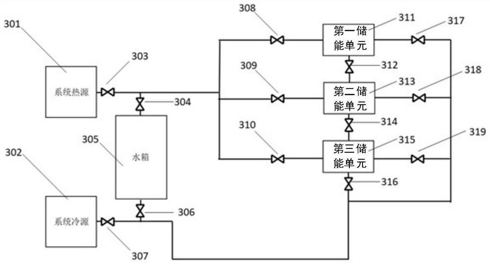
[0021] Example 1: as figure 1 Shown is a schematic diagram of a heat storage device in an embodiment of the present invention, wherein the system heat source 301, the system cold source 302, the system heat source outlet valve 303, the water tank system heat source side valve 304, the water tank 305, the water tank system cold source side valve 306, System cold source outlet valve 307, first energy storage unit inlet valve 308, second energy storage unit inlet valve 309, third energy storage unit inlet valve 310, first energy storage unit 311, first energy storage unit outlet valve 312 , the second energy storage unit 313, the second energy storage unit outlet valve 314, the third energy storage unit 315, the third energy storage unit outlet valve 316, the first energy storage unit another outlet valve 317, the second energy storage unit another One outlet valve 318, and another outlet valve 319 of the third energy storage unit. The phase change material in the energy storage...

Embodiment 2

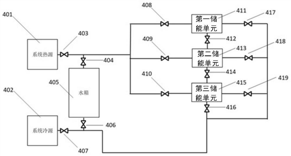
[0024] Example 2: as figure 2 Shown is a schematic diagram of a cold storage device in an embodiment of the present invention, the system heat source 401, the system cold source 402, the system heat source outlet valve 403, the water tank system heat source side valve 404, the water tank 405, the water tank system cold source side valve 406, and the system cold source side valve 406. Source outlet valve 407, first energy storage unit outlet valve 408, second energy storage unit outlet valve 409, third energy storage unit outlet valve 410, first energy storage unit 411, first energy storage unit inlet valve 412, Two energy storage units 413, the second energy storage unit inlet valve 414, the third energy storage unit 415, the third energy storage unit inlet valve 416, the first energy storage unit another inlet valve 417, the second energy storage unit another inlet Valve 418, third energy storage unit inlet valve 419. Among them, for the smooth progress of the cascade cold ...


PUM


Abstract

The invention discloses a variable heat source cascade phase change energy storage control device. The energy storage control device includes: several system heat sources, several system cold sources, several valves, several water tanks and several energy storage units, wherein the system There is at least one valve at the outlet of the heat source, at least one valve at the outlet of the cold source of the system, the water tank includes at least one valve on the heat source side of the system, at least one valve on the cold source side of the system, and the energy storage unit It includes at least one inlet valve, at least two outlet valves, a hot runner, and a space for placing multi-layer phase change materials; the system heat source, the system cold source, the water tank and the energy storage unit through the The valve is connected to the pipeline, and the valve is connected to the pipeline through threads.

Description

technical field [0001] The invention relates to the field of energy storage equipment, in particular to a variable heat source stepped phase change energy storage regulation device. Background technique [0002] The problem of energy crisis is becoming more and more prominent, and the burning of traditional fossil fuels has brought great pollution to the environment. These situations prompt researchers to continuously develop new renewable energy sources to replace traditional energy sources, reduce environmental damage, and expand energy sources. source. However, with the rapid development of the economy and the continuous improvement of people's living standards, the problem of the mismatch between energy demand and supply in time and space also arises. Energy storage unit is one of the key technologies to solve the problem of energy imbalance. Compared with sensible heat energy storage unit, latent heat energy storage unit is equipped with phase change material, so it ha...

Claims


Application Information

Patent Timeline
Patent Type & Authority Patents(China)
IPC IPC(8): F28D20/00F28F27/00
CPCF28D20/0056F28F27/00Y02E60/14
Inventor 徐会金张梓鑫韩兴超赵长颖
Owner SHANGHAI JIAO TONG UNIV
Why Eureka
Try Eureka