
Beam tube sampling head protection device

A protection device and a sampling head technology, applied in the mechanical field, can solve problems such as the bending of the bundle tube and the failure to extract gas normally, and achieve the effect of avoiding clogging

Pending Publication Date: 2021-02-26
SHAANXI COAL CAOJIATAN MINING CO LTD +1
View PDF0 Cites 0 Cited by
  • Summary
  • Abstract
  • Description
  • Claims
  • Application Information

AI Technical Summary

Problems solved by technology

The joint of the tee is at 90 degrees, which often causes the bundle tube to bend at this position, resulting in the gas that cannot be normally extracted into the gob

Method used


Image

  • Beam tube sampling head protection device

Examples


Embodiment Construction

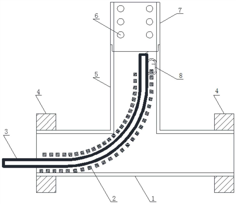
[0018] figure 1 It is a structural schematic diagram of the present invention, as shown in the figure, the bundle tube sampling head protection device in this embodiment includes a bundle tube 3, interconnected horizontal tube sections 1 and vertical tube sections 5, and the bundle tube 3 consists of a horizontal tube section 1 at one end Penetrating until the vertical pipe section 5, the bundle pipe 3 is covered with a support frame 2 for keeping the bundle pipe 3 unimpeded, and the end of the vertical pipe section 5 is detachably provided with a dust-proof ventilation sleeve 7, Prevent the sampling head of the bundle tube 3 from inhaling impurities to cause blockage, and at the same time prevent excessive impurities from entering the bundle tube 3 and affecting the permeability of the bundle tube 3 .

[0019] In this embodiment, the horizontal pipe section 1 and the vertical pipe section 5 form a connected three-way joint form, and the two ends of the horizontal pipe section...


PUM

PropertyMeasurementUnit
diameteraaaaaaaaaa

Abstract

The invention discloses a beam tube sampling head protection device, which comprises a beam tube, a horizontal tube section and a vertical tube section, the horizontal tube section and the vertical tube section are communicated with each other, the beam tube penetrates into the vertical tube section from one end of the horizontal tube section, the beam tube is sleeved with a supporting framework used for keeping the beam tube unblocked, and a dustproof ventilation sleeve is detachably arranged at the tail end of the vertical tube section. According to the beam tube sampling head protection device disclosed by the invention, by arranging the beam tube sampling head in a three-way joint form, accumulated water is prevented from being sucked in the collection process, and meanwhile, by arranging the dustproof ventilation sleeve, large-particle impurities are prevented from entering the beam tube; moreover, a spring is arranged in the three-way connector structure to serve as a framework for supporting the beam tube, so that the bending radius of the beam tube is effectively kept, and the beam tube is prevented from being excessively bent and folded to be blocked to influence gas collection.

Description

technical field [0001] The invention relates to the mechanical field, in particular to a protective device for a sampling head of a bundle tube. Background technique [0002] At present, the method of predicting the possible fire range of the goaf is to divide the spontaneous combustion "three zones" of the goaf, calculate the distribution range of the heat dissipation zone, oxidation zone, and suffocation zone of the goaf, and draw a "distribution map" of the three spontaneous combustion zones to delineate the possible natural range of fire. The commonly used index for dividing the "three zones" of gob spontaneous combustion is mainly the oxygen concentration index, and the index for dividing the heat dissipation zone and the oxidation zone is: the oxygen concentration is 18%. The index for dividing the oxidation zone and the suffocation zone is: the oxygen concentration is 8%. In order to measure the oxygen concentration inside the goaf, bundle tubes are often buried in ...

Claims


Application Information

Patent Timeline
Patent Type & Authority Applications(China)
IPC IPC(8): G01N1/24
CPCG01N1/24
Inventor 杨建辉黄永安李尚国朱兴攀刘国忠李虎存徐俊杨彪管隆刚雷亚军王振兴张义兴王洋丁维波郝建国
Owner SHAANXI COAL CAOJIATAN MINING CO LTD
Learn More