

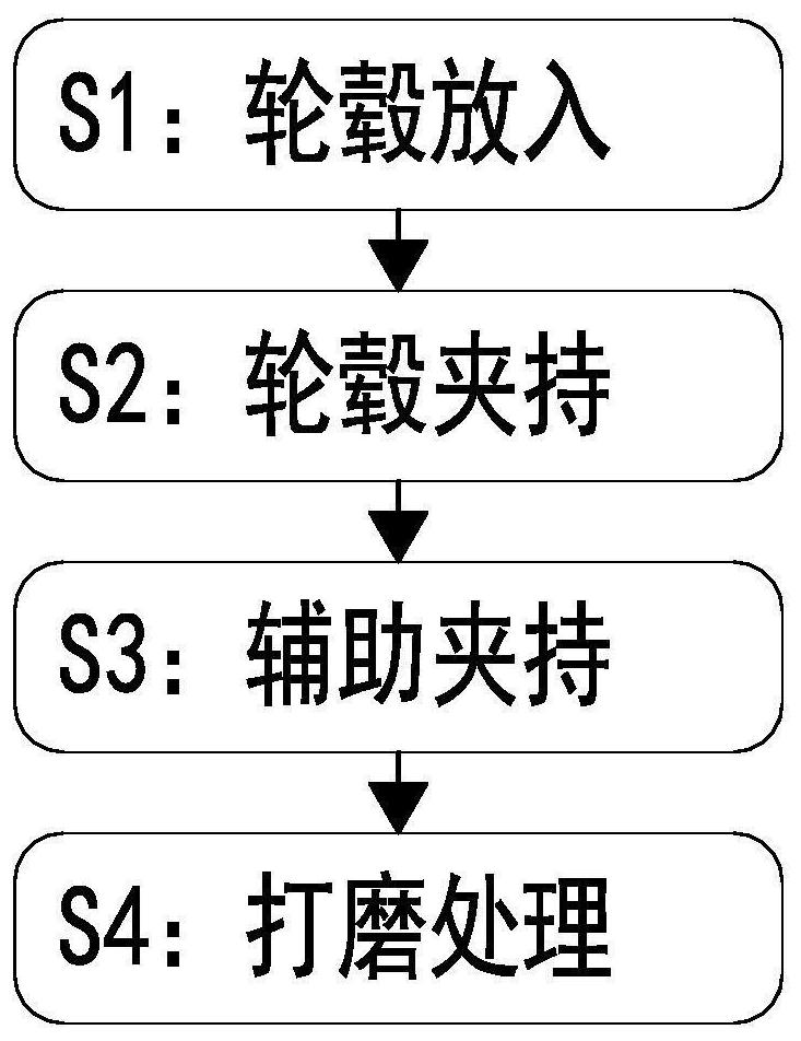
Manufacturing and machining method for new energy automobile alloy hub
A technology for new energy vehicles and processing methods, which is applied in the directions of manufacturing tools, metal processing equipment, grinding workpiece supports, etc., can solve the problem of inconsistent grinding effect, difficulty in grinding the outer surface, and affecting the fit of the alloy wheel and the tire. The appearance effect of the alloy wheel and other problems to achieve the effect of ensuring the quality of the wheel hub and improving the effect
- Summary
- Abstract
- Description
- Claims
- Application Information
AI Technical Summary
Problems solved by technology
Method used
Image

Examples
Embodiment Construction
[0037] The embodiments of the present invention will be described in detail below with reference to the accompanying drawings, but the present invention can be implemented in many different ways defined and covered by the claims.
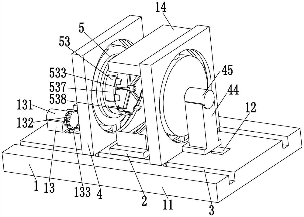
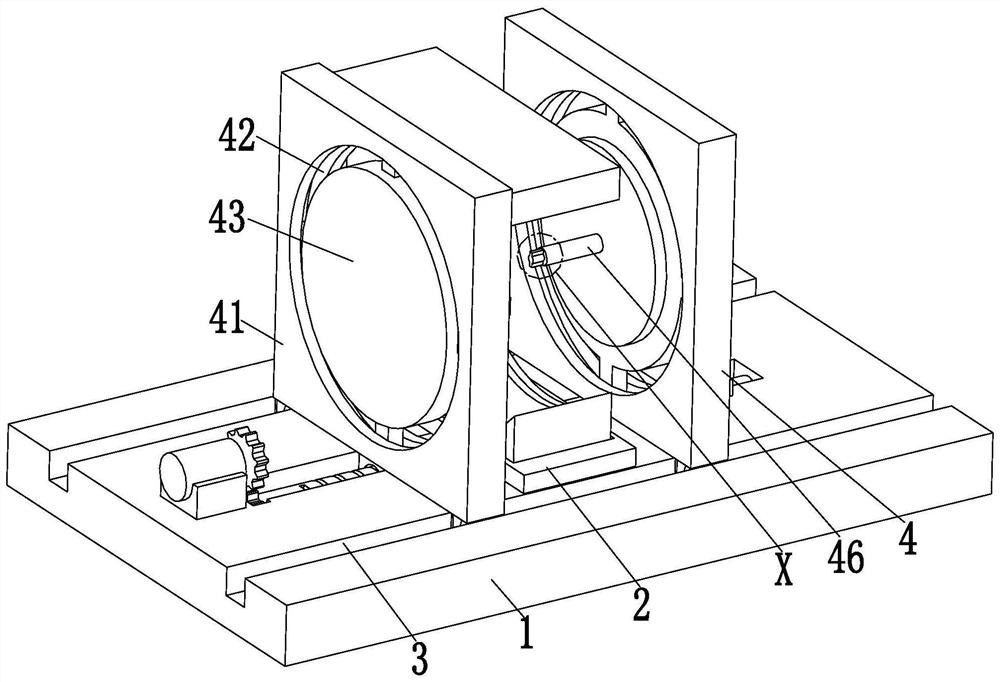
[0038] like Figure 1 to Figure 8 As shown, a new energy vehicle alloy wheel manufacturing method, the process uses the following processing machinery: the machine includes a fixed base 1, a placement table 2, a limit groove 3, a mounting base plate 4 and a clamping device 5, the fixed The middle part of the upper end of the base 1 is equipped with a placement platform 2, and the front and rear sides of the upper end of the fixed base 1 are symmetrically provided with limiting grooves 3, and the left and right sides of the limiting groove 3 are symmetrically slid to be provided with an installation base plate 4, which is located on the left side of the limiting groove 3. A clamping device 5 is installed on the installation base plate 4 .
[0039] T...
PUM
 Abstract
Description
Claims
Application Information