Optical fiber automatic winding and length fixing mechanism based on high-end equipment manufacturing

An equipment and optical fiber technology, which is applied in the field of optical fiber automatic winding and fixed-length mechanism, can solve the problems of reducing labor input, low winding efficiency, and large labor input, and achieves reduced labor input and fixed-length winding volume. , The effect of high winding efficiency

Inactive Publication Date: 2021-03-02
齐小娟
View PDF0 Cites 0 Cited by
  • Summary
  • Abstract
  • Description
  • Claims
  • Application Information

AI Technical Summary

Problems solved by technology

[0005] Aiming at the deficiencies of the prior art, the present invention provides an optical fiber automatic winding and fixed-length mechanism based on high-end equipment, capable of realizing automatic winding of optical fibers, greatly reducing manpower input, high winding efficiency, and fixed length The advantages of long control of the volume of winding, automatic cutting of the op

Method used


Image

  • Optical fiber automatic winding and length fixing mechanism based on high-end equipment manufacturing
  • Optical fiber automatic winding and length fixing mechanism based on high-end equipment manufacturing
  • Optical fiber automatic winding and length fixing mechanism based on high-end equipment manufacturing

Examples


Example Embodiment

[0024]The technical solutions in the embodiments of the present invention will be clearly and completely described below in conjunction with the accompanying drawings in the embodiments of the present invention. Obviously, the described embodiments are only a part of the embodiments of the present invention, rather than all the embodiments. Based on the embodiments of the present invention, all other embodiments obtained by those of ordinary skill in the art without creative work shall fall within the protection scope of the present invention.
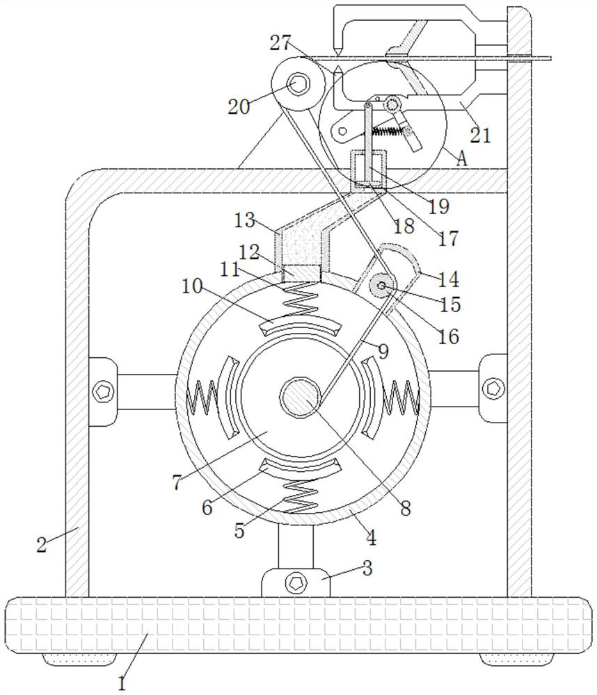
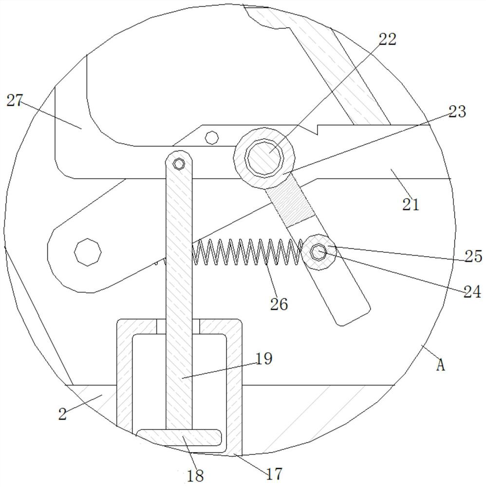
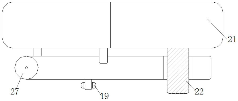
[0025]SeeFigure 1-4, An optical fiber automatic winding and length fixing mechanism based on high-end equipment manufacturing, including a base plate 1, the upper end of the base plate 1 is fixedly connected with a casing 2, the upper end of the casing 2 is fixedly connected with a base, the front end of the base is provided with a shaft, and the outside of the shaft is movable A guide wheel 20 is sleeved. The guide wheel 20 can adjust the dire...


PUM


Abstract

The invention relates to the technical field of optical fiber winding and length fixing, and discloses an optical fiber automatic winding and length fixing mechanism based on high-end equipment manufacturing. The optical fiber automatic winding and length fixing mechanism comprises a bottom plate, a shell is fixedly connected to the upper end of the bottom plate, a support is fixedly connected tothe upper end of the bottom plate and located in the shell, and a circular ring is fixedly connected to the upper end of the support; and first springs are fixedly connected to the bottom ends in thecircular ring, supporting plates are fixedly connected to the upper ends of the first springs, and a rotating wheel is fixedly connected to the upper ends of the supporting plates. The optical fiber automatic winding and length fixing mechanism has the beneficial effects that scissors are driven to rotate through a lifting rod, so that the optical fiber inside a guide wheel is cut off, when the scissors rotate, the scissors drive a second fixing shaft to move leftwards through a rotating plate, the second fixing shaft drives a pre-tightening spring to contract leftwards through a lantern ring,and after the optical fiber cable shearing work is finished, the pre-tightening spring restores to the original length and drives the scissors to reset, so that the effects that the winding efficiency is high, the winding amount can be controlled in a fixed-length mode, and the wound optical fiber can be automatically cut off are achieved.

Description

technical field [0001] The invention relates to the technical field of optical fiber winding and length fixing, in particular to an optical fiber automatic winding and length fixing mechanism based on high-end equipment. Background technique [0002] Optical fiber communication technology stands out from optical communication and has become one of the main pillars of modern communication. It plays a pivotal role in modern telecommunication networks. As an emerging technology, optical fiber communication has developed rapidly in recent years and has a wide range of applications. Rare in the history of communication, it is also an important symbol of the world's new technology revolution and the main transmission tool for various information in the future information society. [0003] The winding of the optical fiber cable is one of the important parts of the later assembly of the optical fiber cable. Due to the long length and soft texture of the optical fiber cable, it is ea...

Claims


Application Information

Patent Timeline
IPC IPC(8): B65H57/14B65H54/54B65H54/70B21F11/00
CPCB21F11/00B65H54/54B65H54/70B65H57/14B65H2701/32
Inventor 齐小娟
Owner 齐小娟
Why Eureka
Try Eureka