Micro-electrolysis treatment and collection device for industrial sewage
A technology for collecting device and industrial sewage, which is applied in the direction of water/sewage treatment, water/sewage treatment equipment, water/sludge/sewage treatment, etc. It can solve the problem of the increase of coagulation time and the inability to discharge micro-electrolyte and micro-electrolyte Waste of micro-electrolysis effect and other issues
- Summary
- Abstract
- Description
- Claims
- Application Information
AI Technical Summary
Problems solved by technology
Method used
Image

Examples
Embodiment Construction
[0020] All features disclosed in this specification, or steps in all methods or processes disclosed, may be combined in any manner, except for mutually exclusive features and / or steps.
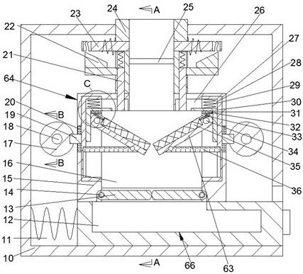
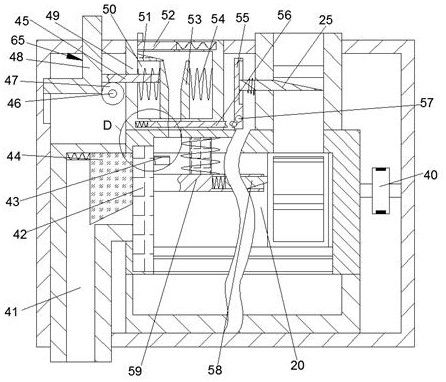
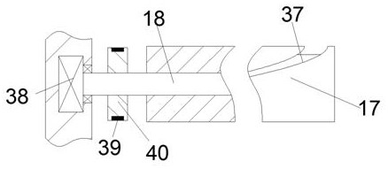
[0021] Combine below Figure 1-6 The present invention is described in detail, and for convenience of description, the orientations mentioned below are now stipulated as follows: figure 1 The up, down, left, right, front and back directions of the projection relationship itself are the same.
[0022] A micro-electrolytic treatment and collection device for industrial sewage of the device of the present invention includes a treatment box 10, and a treatment chamber 11 is provided in the treatment box 10. An adjustment mechanism 65 for mixing an appropriate amount of micro-electrolyte. The adjustment mechanism 65 includes a discharge pipe 24 fixedly installed on the upper end wall of the treatment chamber 11 and connected to the outside of the treatment box 10. The lower end surface of the disc...
PUM
 Abstract
Description
Claims
Application Information